KVH Industries, Inc.
User’s Guide
TracVision
®
TV5
TracVision TV5 User’s Guide
KVH Part # 54-1035 Rev. C
© 2014-2018, KVH Industries, Inc., All rights reserved.
TracVision TV5
User’s Guide
This user’s guide provides all of the basic information you need to
operate, set up, troubleshoot, and maintain the TracVision TV5
system. For detailed installation information, please refer to the
TracVision TV5 Installation Guide.
If you have any comments regarding this manual, please e-mail
them to [email protected]. Your input is greatly appreciated!
Technical Support
North/South America, Australasia:
Phone: +1 401 847-3327
E-mail: [email protected]
Europe, Middle East, Africa, Asia-Pacific:
Phone: +4545160180
E-mail: [email protected]
Trademark Information
TracVision, KVH, and the unique light-colored dome with dark contrasting baseplate (Reg. No.
2,864,752) are trademarks of KVH Industries, Inc.
All other trademarks are the property of their respective owners.
Disclaimer
Every effort has been made to ensure the correctness and completeness of the material in this
document. No company shall be liable for errors contained herein. The information in this
document is subject to change without notice. No warranty of any kind is made with regard to
this material, including, but not limited to, the implied warranties of merchantability and fitness
for a particular purpose.

TracVision TV5 User’s Guide
i
Table of Contents
1 Introduction
Documentation Overview...................................................................3
Important Safety Information.............................................................4
System Overview ...............................................................................5
2 Getting Started
Receiving Satellite TV Signals..........................................................11
Avoiding Blockage ...........................................................................12
Turning On the System ....................................................................13
Accessing the Web Interface ...........................................................14
3 Network Settings
Connecting the TV-Hub to Your Onboard Network...........................17
TV-Hub Ethernet Settings ................................................................19
Connecting to the TV-Hub Using its Built-in Wi-Fi ...........................20
TV-Hub Wireless Settings ................................................................21
Connecting Directly to the TV-Hub Ethernet Port.............................22
Resetting Network Settings to Factory Defaults..............................23
4 Antenna Settings
Adjusting the LNB Skew Angle (Linear Only) ...................................27
Understanding Skew ..............................................................29
Using the Optional NMEA Input........................................................30
Advanced Settings ...........................................................................32
Sleep Mode.............................................................................32
Band/Polarization Control.......................................................32

TracVision TV5 User’s Guide
ii
5 Receiver Settings
Configuring a Linear Receiver for Automatic Switching ..................37
Configuring DIRECTV Receivers for Automatic Switching................38
Allowing External Access on a DIRECTV Receiver ...........................42
Setting the Dish Type on a DIRECTV Receiver .................................43
Running a Check Switch Test on a DISH Network or
Bell TV Receiver ...............................................................................44
Running a Check Switch Test on a Wally Receiver ................46
Check Switch Mode................................................................47
Activating Your Receiver(s)..............................................................48
6 Satellite Settings
Selecting a Single Satellite ..............................................................51
Creating a New Satellite ..................................................................52
Selecting a Satellite Group ..............................................................53
Satellite Elevation Limitations ................................................55
Creating a New Satellite Group........................................................58
Changing Satellites in a Group.........................................................60
Changing Satellite Tracking Parameters .........................................61
7 Switching Satellites
Automatic Satellite Switching for Linear, DISH Network,
or Bell TV..........................................................................................65
Setting Up a Linear Receiver for Automatic Switching...........66
Setting Up a DISH Network/Bell TV Receiver
for Automatic Switching.........................................................67
Setting Up an IP AutoSwitch...................................................68
Automatic Satellite Switching for DIRECTV......................................69
DIRECTV Coax Network Connections......................................70
Additional Equipment for Old DIRECTV Receivers ..................71

TracVision TV5 User’s Guide
iii
Setting Up a DIRECTV Receiver for Automatic Switching.......73
Understanding DIRECTV SWM Technology.............................74
Selecting Automatic Switching Mode..............................................76
Selecting the Master Receiver.........................................................77
Manual Satellite Switching..............................................................78
Tri-Americas Satellite Switching .....................................................79
8 Troubleshooting
Basic Checks ...................................................................................83
Status Information on the Home Page.............................................85
TV-Hub Status Indicators.................................................................87
IP AutoSwitch Status Indicator ........................................................90
Error Messages................................................................................91
System Logs ....................................................................................95
Operational Log ......................................................................96
Event Log................................................................................97
System Information .........................................................................98
Technical Support..........................................................................100
9 Maintenance
Preventive Maintenance ................................................................103
Updating the Satellite Library ........................................................104
Updating the Software...................................................................106
Corrective Maintenance.................................................................108
Restarting the System ...................................................................109
ASpecifications
System Specifications ...................................................................113
TracVision TV5 User’s Guide
1
Introduction
1. Introduction
This section provides important safety information you need to know
before using the system. It also provides an overview of the system and
its documentation.
Contents
Documentation Overview ..................................................................................3
Important Safety Information ............................................................................4
System Overview...............................................................................................5
TracVision TV5 User’s Guide
3
Introduction
Documentation Overview
The information provided here contains complete operation,
configuration, and troubleshooting details for your TracVision system.
Icons Used
The documentation for this product uses the following icon:
Related Documentation
In addition to the Help accessible from the TV-Hub’s web interface,
the following documents are provided with your TracVision system:
Icon Description
This is a danger, warning, or caution notice. Be sure
to read these carefully to avoid injury!
Document Description
Installation Guide Complete installation instructions
Quick Start Guide Handy quick reference guide with
basic operating instructions
Installation Checklist Form that the installer must return to
validate the quality of the installation
Mounting Templates Templates that the installer uses to
lay out the mounting holes for the
antenna and the TV-Hub
Warranty Statement Warranty terms and conditions
Kitpack Contents List List of every part supplied in the kit
TracVision TV5 User’s Guide
4
Introduction
Important Safety Information
For your own safety, and for the safety of your passengers and/or
crew, be sure to read the following important notices.
WARNING
Risk of Electric Shock
To avoid electric shock, do not open the TV-Hub’s chassis
enclosure. There are no user-serviceable parts inside.
WARNING
Risk of Electric Shock
If any component of the TracVision system becomes damaged and/
or no longer functions normally, disconnect it from power, secure it
from unintended operation, and contact KVH Technical Support
(see “Technical Support” on page 100). All repairs or modifications
must be performed by a trained, KVH-certified technician.
WARNING
Risk of Explosion
Do not operate the TV-Hub (or any other electrical device) in an
environment where flammable gases, vapors, or dusts are present.
In addition, do not use the TV-Hub in an environment with a
temperature outside its 5°F to 131°F (-15°C to 55°C) operating
range.
WARNING
Risk of Electric Shock
Failure to ground the TracVision system properly may cause an
unsafe floating ground condition, risking potentially lethal electric
shock. Refer to the Installation Guide for details on the proper
grounding of the equipment.
TracVision TV5 User’s Guide
5
Introduction
System Overview
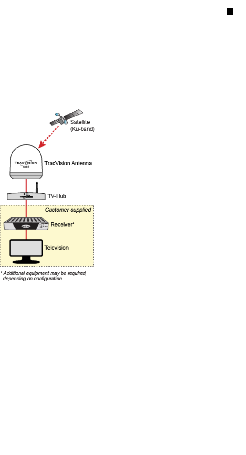
Your TracVision system is a state-of-the-art, actively stabilized
antenna system that delivers live satellite TV to your mobile audio/
video entertainment system. A basic system is illustrated below. Refer
to the Installation Guide for detailed wiring diagrams.
Figure 1-1 Basic TracVision System Diagram
TracVision TV5 User’s Guide
6
Introduction
The TracVision system includes the following components:
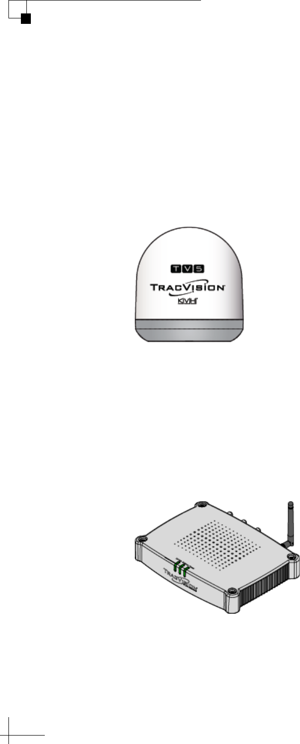
Antenna
Housed within a protective radome, the antenna quickly acquires and
tracks the desired satellite to deliver a crystal-clear television picture,
even while you’re on the move. Its built-in DVB-S2 technology ensures
compatibility with all modern Ku-band television satellites, and its
exclusive RingFire technology provides stronger signals, wider
coverage, and better reception.
Figure 1-2 Antenna
TV-Hub
The IP-enabled TV-Hub powers and controls the antenna. With its
Ethernet connection and built-in Wi-Fi, you can access its easy-to-use
web interface from any mobile device, allowing you to set up, operate,
and monitor all aspects of the system. Its built-in library of over 100
satellites is fully customizable, and can even be updated over the
Internet.
Figure 1-3 TV-Hub

TracVision TV5 User’s Guide
7
Introduction
There are three possible versions of TV-Hub:
• TV-Hub A+: Supplied with North American systems
starting in the spring of 2018; includes a built-in DIRECTV
digital SWM (single wire multiswitch) with its associated
DSWM connector on the rear panel that supports up to 13
tuners; also supports DISH Network and Bell TV services
• TV-Hub A: Supplied with North American systems prior
to 2018; includes a built-in DIRECTV SWM (single wire
multiswitch) with its associated SWM connector on the rear
panel that supports up to eight tuners; also supports DISH
Network and Bell TV services
• TV-Hub B: Supplied with linear, DIRECTV Latin America,
and Tri-Americas systems; does not include DIRECTV
SWM component/connector(s); identical to TV-Hub A+ or
A otherwise, so it can also support DISH Network and Bell
TV services
Figure 1-4 TV-Hub Versions

TracVision TV5 User’s Guide
9
Getting Started
2. Getting Started
This section explains how to turn on the system for the first time and
access the web interface.
Contents
Receiving Satellite TV Signals .........................................................................11
Avoiding Blockage ...........................................................................................12
Turning On the System ....................................................................................13
Accessing the Web Interface...........................................................................14
TracVision TV5 User’s Guide
11
Getting Started
Receiving Satellite TV Signals
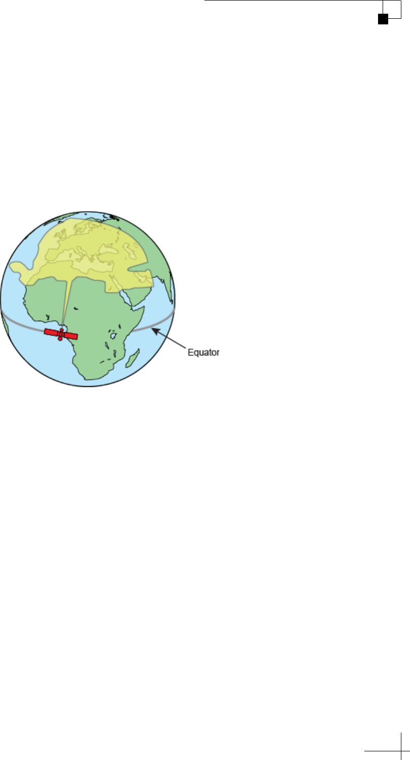
Television satellites are located in fixed positions above the Earth’s
equator and beam TV signals down to the earth within certain regions
that they serve. Therefore, to receive TV signals from a given satellite,
you must be located within that satellite’s unique coverage area, also
known as its “footprint.” To view the latest TracVision satellite
coverage maps, visit KVH’s website at www.kvh.com/footprint.
Figure 2-1 Example of a Satellite Footprint
The size of the antenna makes a big difference in determining which
satellites it can track and where. Larger antennas have the following
advantages over smaller models:
• Collects more signal: As you move further away from the
center of a satellite footprint, the power level, referred to as
EIRP (effective isotropic radiated power), gradually fades,
just like a radio station. Larger antennas can pull in more of
the weak signal, so they can track a satellite at a lower EIRP
than smaller antennas.
• Narrower beamwidth: Some satellites are very close
together in the sky, separated by only a few degrees in
longitude. Larger antennas receive signals within a
narrower beam, reducing the chance of interference caused
by transmissions from adjacent satellites.
TracVision TV5 User’s Guide
12
Getting Started
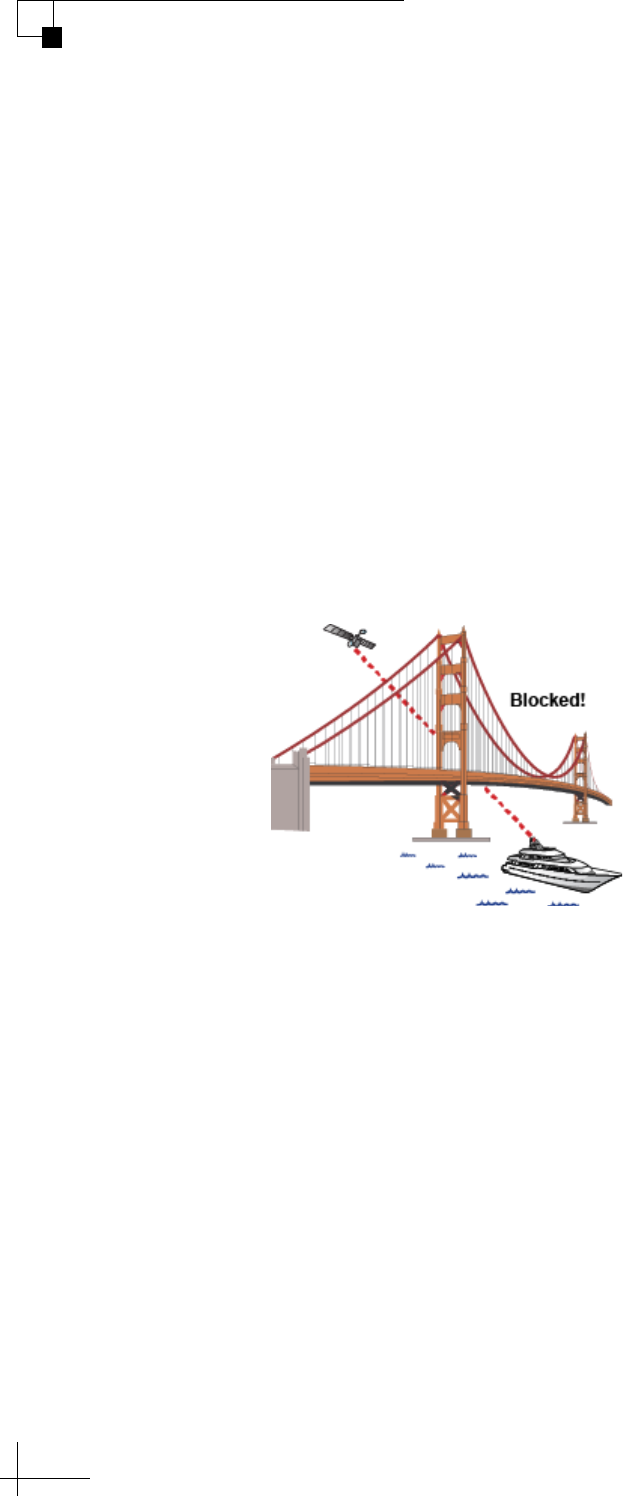
Avoiding Blockage
Since satellites are located 22,300 miles (35,900 km) above the equator,
the TracVision antenna must have a clear view of the sky to receive
satellite TV signals. Anything that stands between the antenna and the
satellite can block the signal, resulting in lost reception. Common
causes of blockage include the following:
• Trees, buildings, and bridges
• Other vessels docked alongside your vessel
• Onboard masts, antennas, or other structures
Severe weather conditions or excessive dirt on the antenna can also
affect reception.
Figure 2-2 Example of Satellite Blockage
TracVision TV5 User’s Guide
13
Getting Started
Turning On the System
To turn on your TracVision system, follow these steps:
1. Make sure the antenna has a clear, unobstructed view of the
sky.
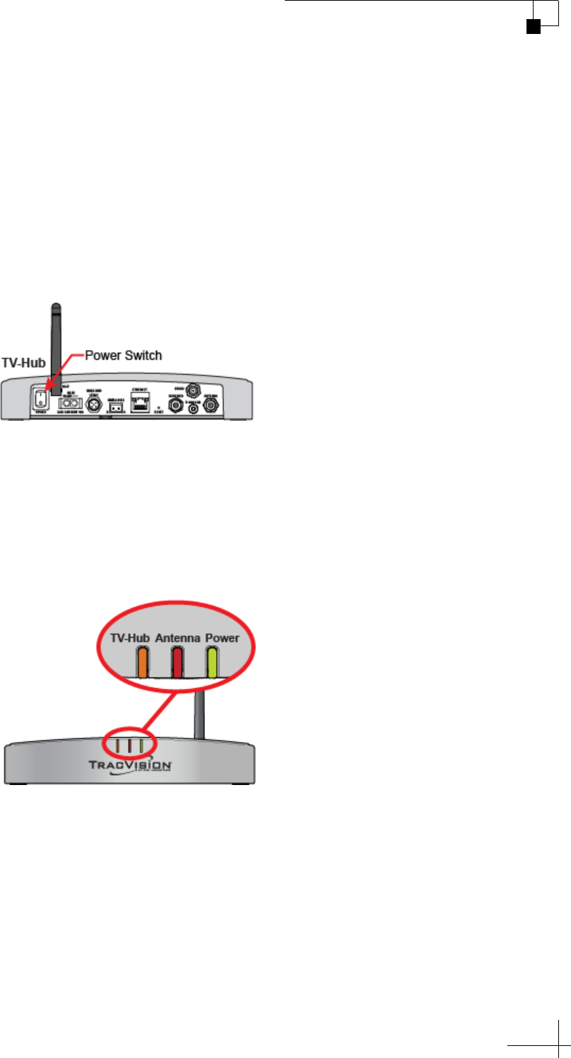
2. At the rear panel of the TV-Hub, set the power switch to the On
(|) position. The TV-Hub supplies power to the antenna.
Figure 2-3 Power Switch (TV-Hub A+ shown)
3. Wait a few minutes for system startup.
4. Once the antenna finds the selected satellite, all three status
lights on the TV-Hub should be lit green. If any lights are not lit
green, refer to “TV-Hub Status Indicators” on page 87.
Figure 2-4 Status Lights
TracVision TV5 User’s Guide
14
Getting Started
Accessing the Web Interface
The TV-Hub’s web interface allows you to check system status, switch
satellites and master receiver, update software and the satellite library,
and configure all aspects of the system. To access the web interface
using any Wi-Fi-enabled mobile device (such as a smartphone, tablet,
or laptop), follow these steps:
1. Select the TVHub-<TV-Hub serial number> network from
your device’s Wi-Fi settings to connect to the TV-Hub.
2. Start your web browser and enter http://tvhub.kvh. As long as
the TV-Hub is turned on and functioning properly, the Home
page will appear in your browser. (If the web interface does not
appear, try entering http://172.16.0.1, which is the default IP
address of the TV-Hub.) For details on the information
provided on the home page, see “Status Information on the
Home Page” on page 85.
Figure 2-5 Wireless Connection to TV-Hub Web Interface
NOTE: If the TV-Hub is connected to an onboard network, you may also
access the web interface over the network by entering the TV-Hub’s IP
address in your browser. (You can find the IP address on the Settings page of
the web interface. See “TV-Hub Ethernet Settings” on page 19).

TracVision TV5 User’s Guide
15
Network Settings
3. Network Settings
This section explains the various ways you can connect to the TV-Hub to
access the web interface. It also explains how to connect the TV-Hub to
an onboard network.
Contents
Connecting the TV-Hub to Your Onboard Network ..........................................17
TV-Hub Ethernet Settings ................................................................................19
Connecting to the TV-Hub Using its Built-in Wi-Fi...........................................20
TV-Hub Wireless Settings ................................................................................21
Connecting Directly to the TV-Hub Ethernet Port ............................................22
Resetting Network Settings to Factory Defaults..............................................23
TracVision TV5 User’s Guide
17
Network Settings
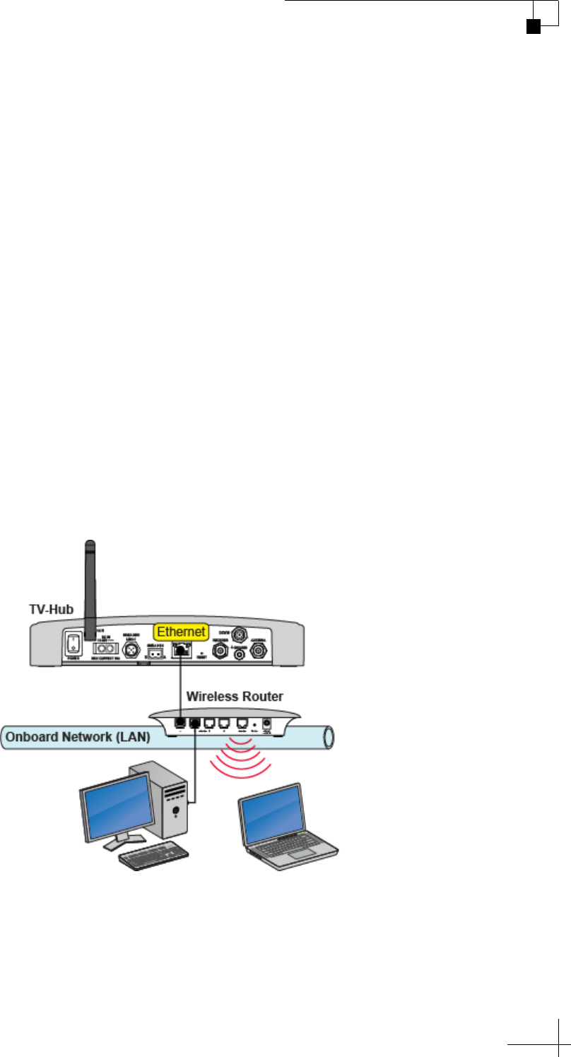
Connecting the TV-Hub to Your Onboard Network
You can connect the TV-Hub to an onboard local area network (LAN).
A network connection is necessary if either of the following conditions
apply:
• You have one or more IP AutoSwitches installed to enable
automatic satellite switching (Linear/DISH Network/Bell TV
only).
• You want to have the ability to access the TV-Hub’s web
interface using any device connected to your onboard
network.
By default, the TV-Hub’s Ethernet port is configured as a DHCP client,
which means your network’s router will automatically assign it an IP
address. Simply connect the TV-Hub’s Ethernet port to your onboard
network then turn on the TV-Hub.
NOTE: Use a straight-through 100 Mbps fast Ethernet UTP CAT5 cable (or
better) with RJ45 connectors.
Figure 3-1 TV-Hub Wired Network Connection (TV-Hub A+ shown)
Once the TV-Hub is connected to your onboard network, you can
access its web interface by entering the TV-Hub’s dynamically
assigned IP address in the web browser of any device connected to the
network. You can find the TV-Hub’s IP address on the web interface
(select Settings > Network Settings).

TracVision TV5 User’s Guide
18
Network Settings
If Bonjour is installed on your device, you can use it to find the
TV-Hub on the onboard network without knowing the IP address. Just
search for its host name: TVHub-<TV-Hub serial number>. For more
information about Bonjour, visit www.apple.com/support/bonjour.
NOTE: In Dynamic (DHCP) mode, the TV-Hub could get assigned a
different IP address whenever it is turned on. If you prefer, you can assign a
static IP address to the TV-Hub that never changes, even after a reboot. See
“TV-Hub Ethernet Settings” on page 19 for details.
Connecting the TV-Hub to Your Onboard Network Using its Built-in
Wi-Fi
Although not recommended, you can modify the TV-Hub’s wireless
settings to connect to your onboard network using its Wi-Fi antenna,
rather than using an Ethernet cable. However, once you change the
TV-Hub’s wireless settings from Access Point mode to Infrastructure
mode, you will lose the ability to connect directly to the TV-Hub using
your mobile device – you will always have to connect via the network.
See “TV-Hub Wireless Settings” on page 21 for details.
TracVision TV5 User’s Guide
19
Network Settings
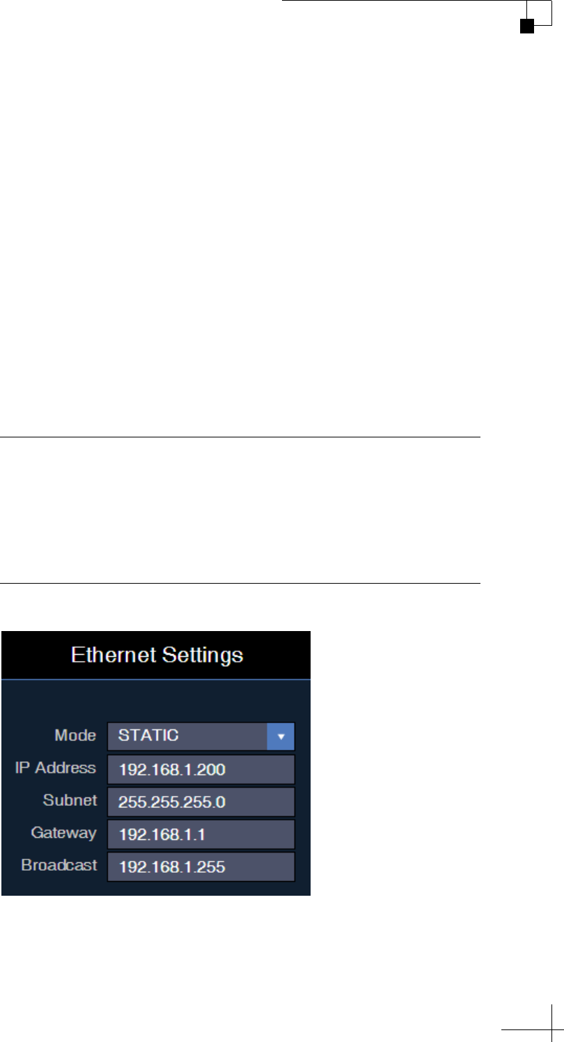
TV-Hub Ethernet Settings
By default, the Ethernet port of the TV-Hub is configured for Dynamic
mode. This means that, when the TV-Hub is connected to an onboard
network, the network’s router assigns it an IP address. Most routers
are normally configured as a DHCP (dynamic host configuration
protocol) server.
NOTE: On startup, if the TV-Hub does not detect a DHCP server within a
few seconds, it automatically assigns itself a static IP address: 169.254.253.1.
If you want to assign a specific IP address to the TV-Hub, you can
configure the TV-Hub for Static mode at the Settings page of the web
interface (go to Settings > Network Settings). When you select Static
mode, you will need to enter the desired IP address, along with its
associated subnet, gateway address, and broadcast address. These
settings require networking expertise.
Figure 3-2 Ethernet Settings
Important!
If your system is set up for automatic satellite switching for DIRECTV,
make sure your DIRECTV receiver(s) have IP addresses in the same
subnet as the TV-Hub. If your system includes IP AutoSwitches for
automatic satellite switching, make sure they are all on the same local
LAN segment as the TV-Hub.
TracVision TV5 User’s Guide
20
Network Settings
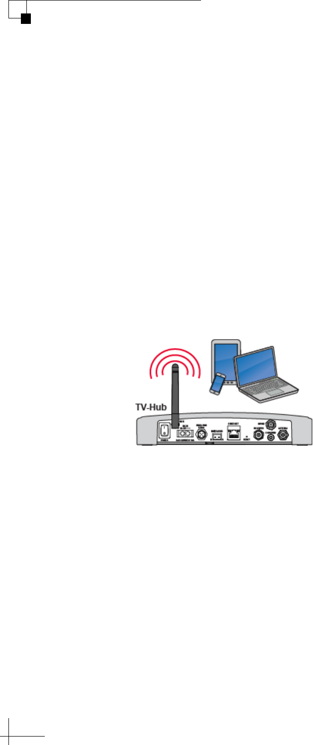
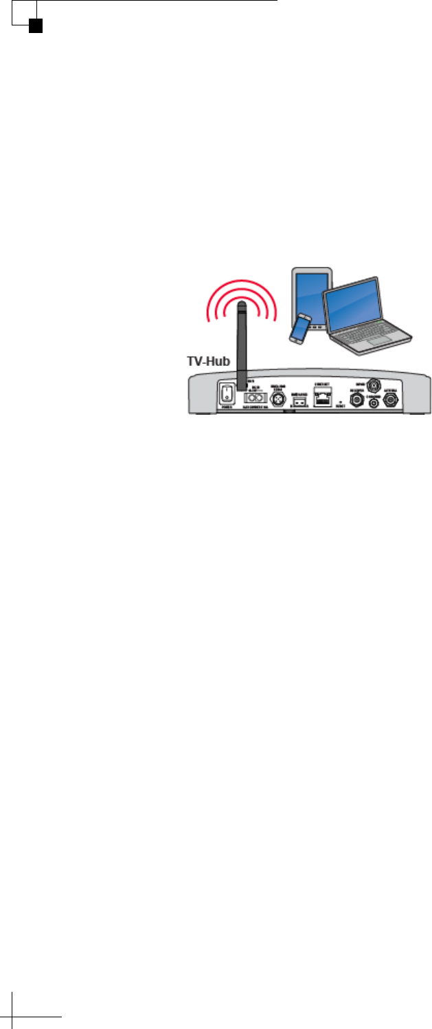
Connecting to the TV-Hub Using its Built-in Wi-Fi
You can connect any Wi-Fi enabled mobile device (such as a
smartphone, tablet, or laptop) to the TV-Hub via its built-in wireless
access point (WAP). The wireless range will depend on the layout and
structure of the vessel. For example, wireless signals degrade when
passing through bulkheads, water, and near metal masses.
Figure 3-3 TV-Hub Wi-Fi Connection (TV-Hub A+ shown)
NOTE: This direct wireless connection will not work if you changed the
TV-Hub’s wireless settings from Access Point mode to Infrastructure.
To access the TV-Hub’s web interface via Wi-Fi, follow these steps:
1. Select the TVHub-<TV-Hub serial number> network from
your device’s Wi-Fi settings to connect to the TV-Hub.
2. Start your web browser and enter http://tvhub.kvh. (If the web
interface does not appear, try entering http://172.16.0.1, which
is the default IP address of the TV-Hub.)
TracVision TV5 User’s Guide
21
Network Settings
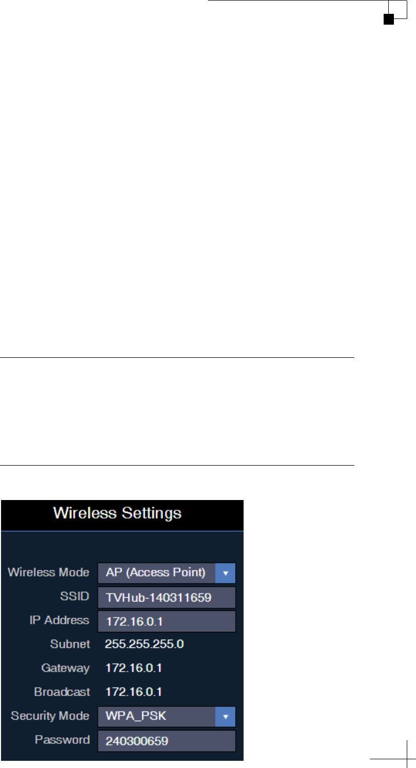
TV-Hub Wireless Settings
By default, the TV-Hub’s wireless settings are configured for the
following:
• Wireless Mode: AP (Access Point)
• SSID: TVHub-<TV-Hub serial number>
• IP address: 172.16.0.1
•Security Mode: Off
You can change any of these settings at the Settings page of the web
interface (go to Settings > Network Settings).
KVH strongly advises that you select the WPA_PSK security mode
and assign a unique password to prevent unauthorized access. If you
keep the default settings, you’re allowing anyone to access the
TV-Hub with their mobile device.
Figure 3-4 Wireless Settings with Security Applied
Important!
If you select Infrastructure (IF) mode to connect the TV-Hub to your
onboard network, you will no longer be able to access the TV-Hub’s
web interface directly – you will have to go through the network.
Therefore, KVH strongly recommends that you keep the TV-Hub set to
Access Point (AP) wireless mode.
TracVision TV5 User’s Guide
22
Network Settings
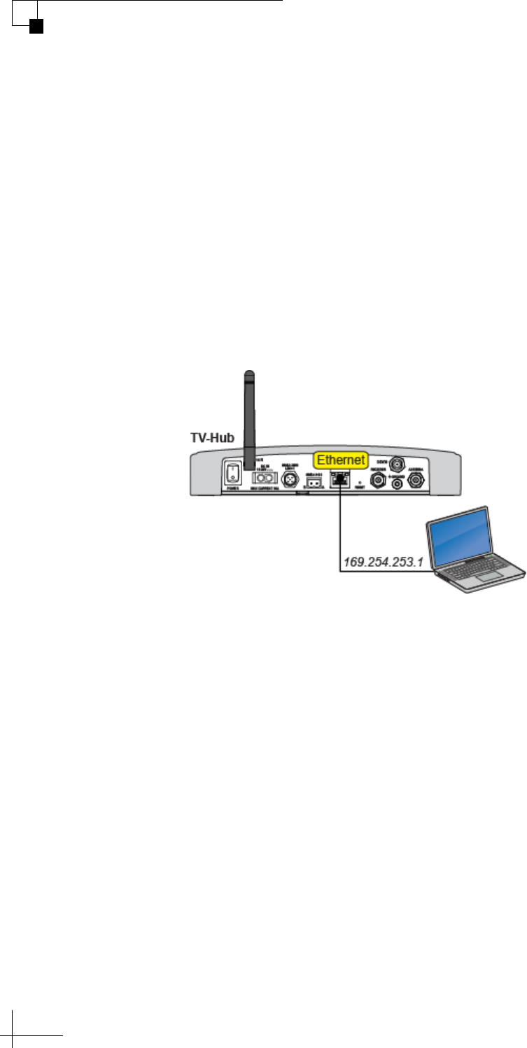
Connecting Directly to the TV-Hub Ethernet Port
You can connect a computer directly to the “Ethernet” port on the back
of the TV-Hub. This option allows you to access the TV-Hub web
interface if you do not have a Wi-Fi-enabled device and you do not
wish to connect the TV-Hub to an onboard network.
NOTE: Use a straight-through 100 Mbps fast Ethernet UTP CAT5 cable (or
better) with RJ45 connectors.
Once you have connected your computer, enter http://169.254.253.1
into your web browser to access the TV-Hub’s web interface.
Figure 3-5 TV-Hub Direct Wired Connection (TV-Hub A+ shown)
TracVision TV5 User’s Guide
23
Network Settings
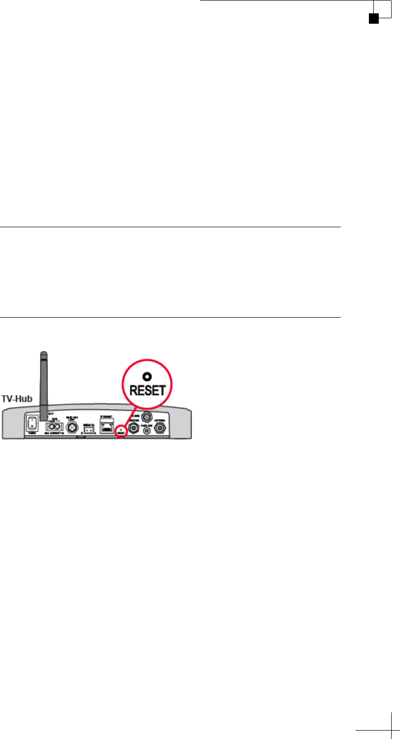
Resetting Network Settings to Factory Defaults
If the TV-Hub’s network configuration becomes corrupted such that
you can no longer access the web interface, you can reset all of the
network settings to their original factory settings.
To reset the network settings to factory defaults, use a paper clip or
pencil to press and hold the Reset button on the rear panel of the
TV-Hub. Hold the button for about 5 seconds then release. KVH
recommends that you restart the system following a reset (see
“Restarting the System” on page 109.)
Figure 3-6 Reset Button (TV-Hub A+ shown)
Important!
Resetting the network settings will turn off wireless security and clear
your password. Be sure to reapply security settings to prevent
unauthorized access. See “TV-Hub Wireless Settings” on page 21 for
details.

TracVision TV5 User’s Guide
25
Antenna Settings
4. Antenna Settings
This section explains how to adjust the skew of a linear LNB, configure
the antenna to use a NMEA input, and modify advanced settings.
Contents
Adjusting the LNB Skew Angle (Linear Only)...................................................27
Using the Optional NMEA Input........................................................................30
Advanced Settings...........................................................................................32
TracVision TV5 User’s Guide
27
Antenna Settings
Adjusting the LNB Skew Angle (Linear Only)
Unless your antenna is equipped with automatic skew, you need to
manually adjust the LNB’s skew angle to optimize signal reception
whenever you change your geographic location or select a different
satellite. (To learn more about skew, see “Understanding Skew” on
page 29.) To set the skew angle, follow these steps:
1. Launch the Setup Wizard from the web interface (go to Settings
> General Settings).
2. Unless the TracVision antenna is receiving position
information from a NMEA device, manually enter your current
position at the Setup Wizard.
3. At the Setup Wizard, note the displayed skew angle for the
selected satellite.
4. Turn off the TV-Hub to remove power from the TracVision
antenna.
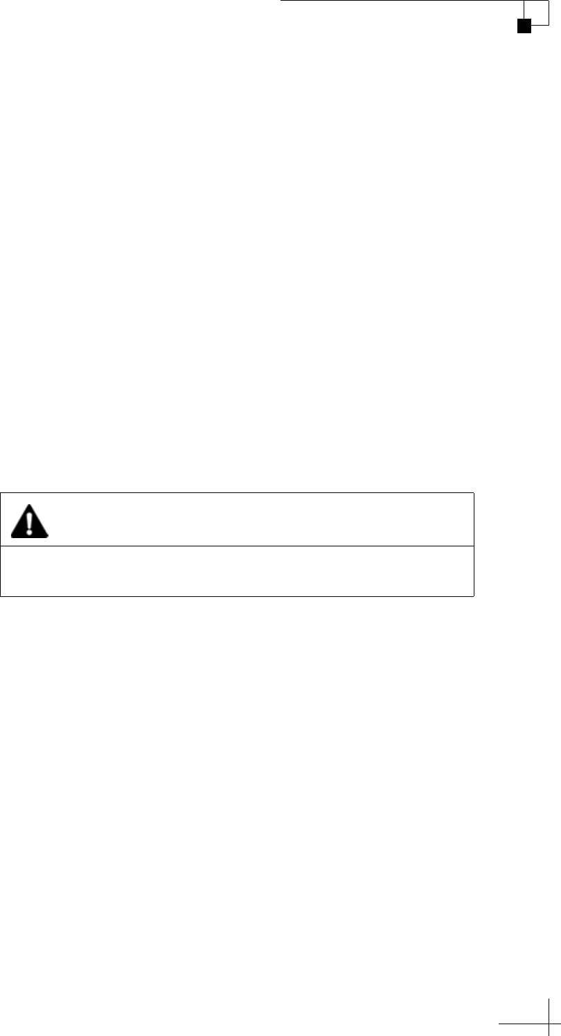
5. Remove the Phillips-head screws securing the radome to the
antenna. Then carefully lift the radome straight up until clear
of the antenna assembly and set it aside in a safe place.
NOTE: Do not place the radome on a hot metal surface – the heat may warp
the radome.
CAUTION
For your own safety, make sure the TracVision system is powered
off before you perform any work on the antenna.
TracVision TV5 User’s Guide
28
Antenna Settings
Figure 4-1 Radome Removal
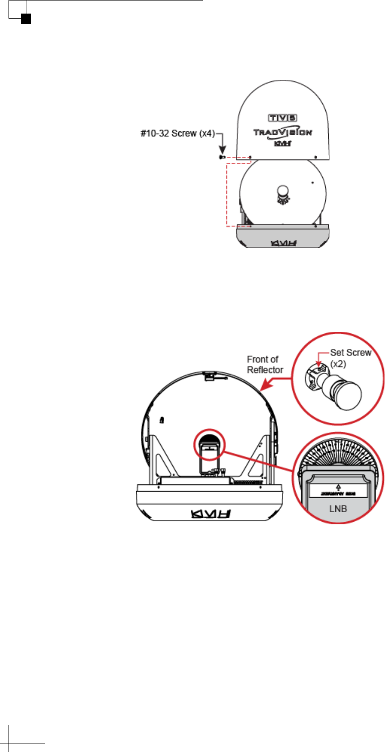
6. Using a 2mm Allen hex key, loosen (but do not remove) the
two M4 socket set screws securing the LNB to the reflector.
Figure 4-2 LNB Skew Adjustment
7. Rotate the LNB clockwise or counter-clockwise until the arrow
on the LNB points to the correct skew angle printed on the
choke feed.
NOTE: Be sure to keep the LNB fully inserted into the choke feed to ensure
optimum performance.
8. Tighten the set screws to secure the LNB in place. Apply
11 in.-lbs (1.2 N-m) of torque, if possible.
9. Reinstall the radome.
TracVision TV5 User’s Guide
29
Antenna Settings
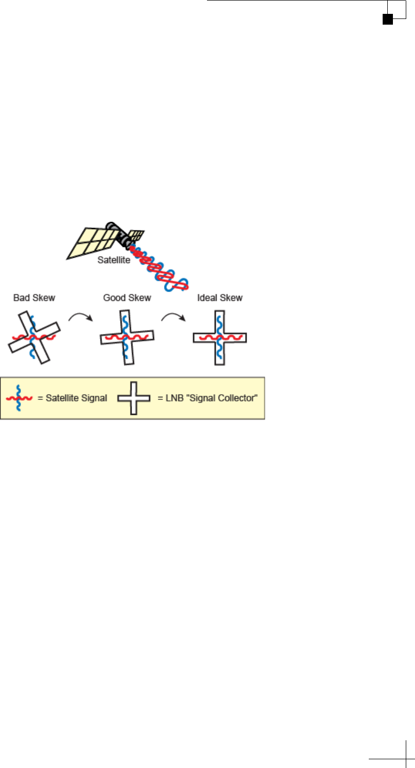
Understanding Skew
Linearly polarized satellite signals are transmitted in vertical and
horizontal “waves” offset exactly 90° from each other. Since these
signals are oriented in a precise cross pattern, the TracVision antenna’s
receiving element, called the LNB, must be oriented in the same way.
This orientation is referred to as the LNB’s “skew angle.” The more
precise the LNB’s skew, the more signal it will collect and the better
the reception.
Figure 4-3 How Skew Works
TracVision TV5 User’s Guide
30
Antenna Settings
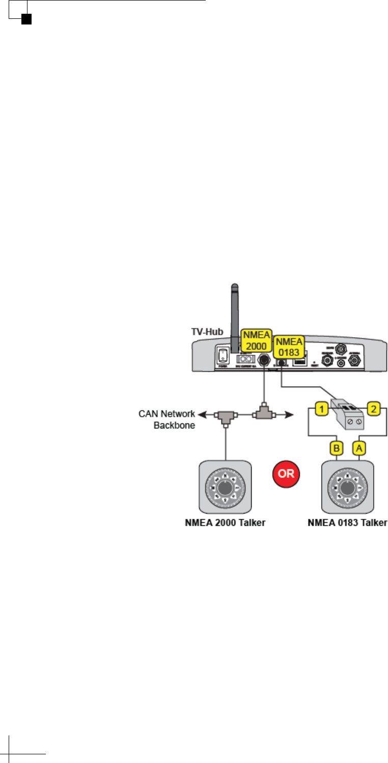
Using the Optional NMEA Input
If a NMEA device is connected to the TV-Hub, the antenna can use its
GNSS position and heading data to speed up satellite acquisition.
(Refer to the Installation Guide for details on connecting the NMEA
device.) The current position and true heading will also be displayed
on the Home page of the web interface. (If magnetic heading is supplied
to the TV-Hub, the TV-Hub converts it to true heading.)
If the antenna is equipped with a built-in GPS, it will use the NMEA
device as a backup source of position data. The Home page will
display position data from the built-in GPS unless it switches to the
NMEA backup.
Figure 4-4 TV-Hub NMEA Connections (TV-Hub A+ shown)
NOTE: TV-Hubs built after August 2014 are equipped with the NMEA 2000
connector.
TracVision TV5 User’s Guide
31
Antenna Settings
To configure the system to use data from a connected NMEA device,
follow these steps:
1. To use a NMEA 0183 device, configure it to transmit one or
more of the following messages at 4800 baud:
To use a NMEA 2000 device, configure it to transmit one or more
of the following messages via the CAN network:
2. Select the NMEA source at the TracVision Setup Wizard. You
can launch the Setup Wizard from the web interface (go to
Settings > General Settings).
$--xxx Message Description
HDG Heading, Deviation and Variation
HDM Heading, Magnetic
HDT Heading, True
OSD Own Ship Data
THS True Heading and Status
VHW Water Speed and Heading
RMC GNSS Position Data
PGN Description
127250 Vessel Heading
129029 GNSS Position Data

TracVision TV5 User’s Guide
32
Antenna Settings
Advanced Settings
The following advanced settings enhance the performance of the
TracVision antenna system:
• Sleep Mode (see “Sleep Mode” on page 32)
• Band/Polarization Control (see “Band/Polarization
Control” on page 32)
Although the factory default settings work well in most cases, you can
change any of them at the web interface (go to Settings > Advanced
Settings).
Sleep Mode
When you are moving, the antenna’s motors need to run continuously
to keep the antenna pointed at the satellite and locked onto the peak
signal. However, if you are stationary, the motors don’t need to run
since the antenna’s orientation to the satellite doesn’t change. In these
stationary conditions, Sleep mode locks the antenna in place and shuts
down the motors to conserve power and silence the antenna.
KVH recommends that you keep Sleep mode set to On (default
setting).
Band/Polarization Control
Linear satellite TV channels can be carried on any of a satellite’s four
combinations of frequency band and polarization. Since only one of
these four signals can be delivered to a receiver at any one time, the
receiver sends a voltage/tone on its coax cable to request the band/
polarization for the currently selected channel:
Voltage Tone Polarization Band
13 VDC Off Vertical Low
18 VDC Off Horizontal Low
13 VDC On Vertical High
18 VDC On Horizontal High
TracVision TV5 User’s Guide
33
Antenna Settings
With Band/Polarization Control set to Master Receiver (default
setting), the satellite signal output of the TV-Hub’s “Receiver” port is
the polarization and band that is currently selected by the master
receiver. This setting is recommended for most configurations and
ensures the antenna always receives a valid band/polarization on
which to track the satellite.
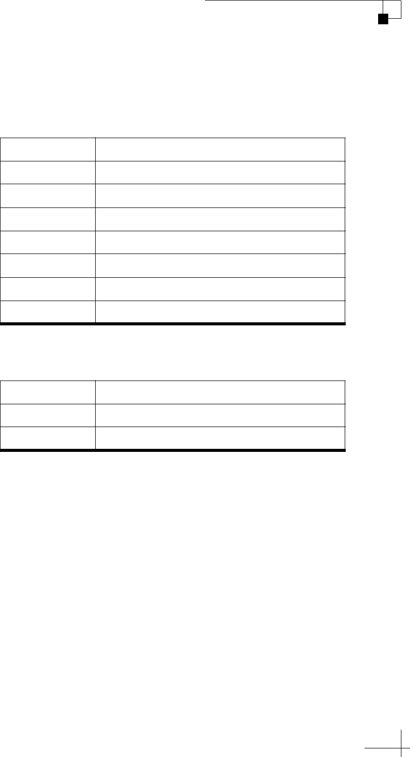
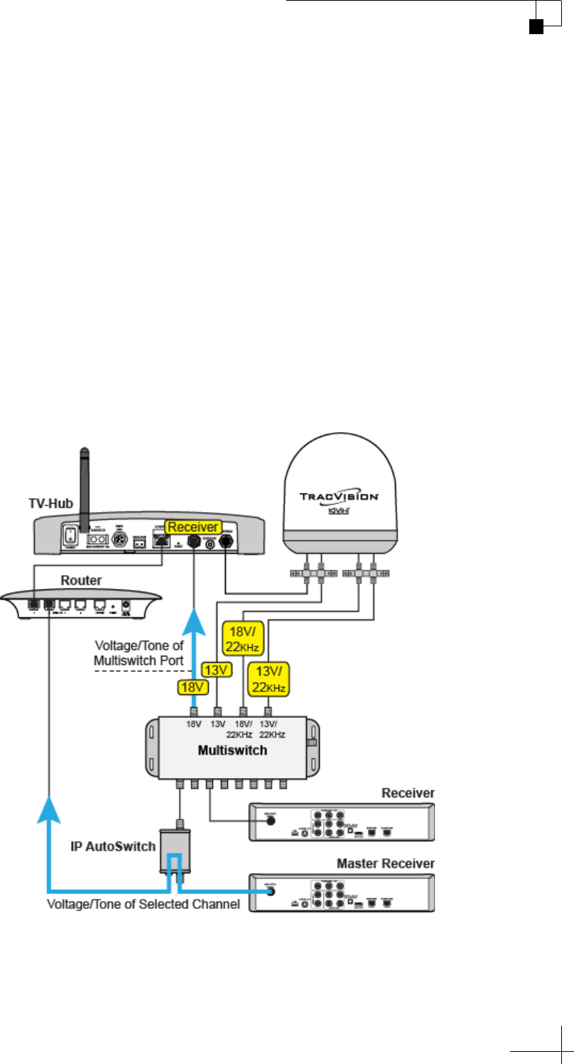
If you have a linear configuration with a multiswitch and one or more
IP AutoSwitches installed, KVH recommends that you set Band/
Polarization Control to TV-Hub. In this configuration, the TV-Hub
ignores the voltage/tone from the master receiver and outputs
whichever polarization/band corresponds to the voltage/tone that is
present on the coax cable connected to its “Receiver” port. This allows
the multiswitch to continue receiving all four combinations of band/
polarization from the antenna.
Figure 4-5 Example of Conflicting Band/Polarization Requests

TracVision TV5 User’s Guide
35
Receiver Settings
5. Receiver Settings
This section explains how to set up various types of satellite TV receivers
to operate with the TracVision system. For receiver wiring details, refer
to the Installation Guide.
Contents
Configuring a Linear Receiver for Automatic Switching..................................37
Configuring DIRECTV Receivers for Automatic Switching ...............................38
Allowing External Access on a DIRECTV Receiver ...........................................42
Setting the Dish Type on a DIRECTV Receiver .................................................43
Running a Check Switch Test on a DISH Network or Bell TV Receiver............44
Activating Your Receiver(s)..............................................................................48
TracVision TV5 User’s Guide
37
Receiver Settings
Configuring a Linear Receiver for Automatic
Switching
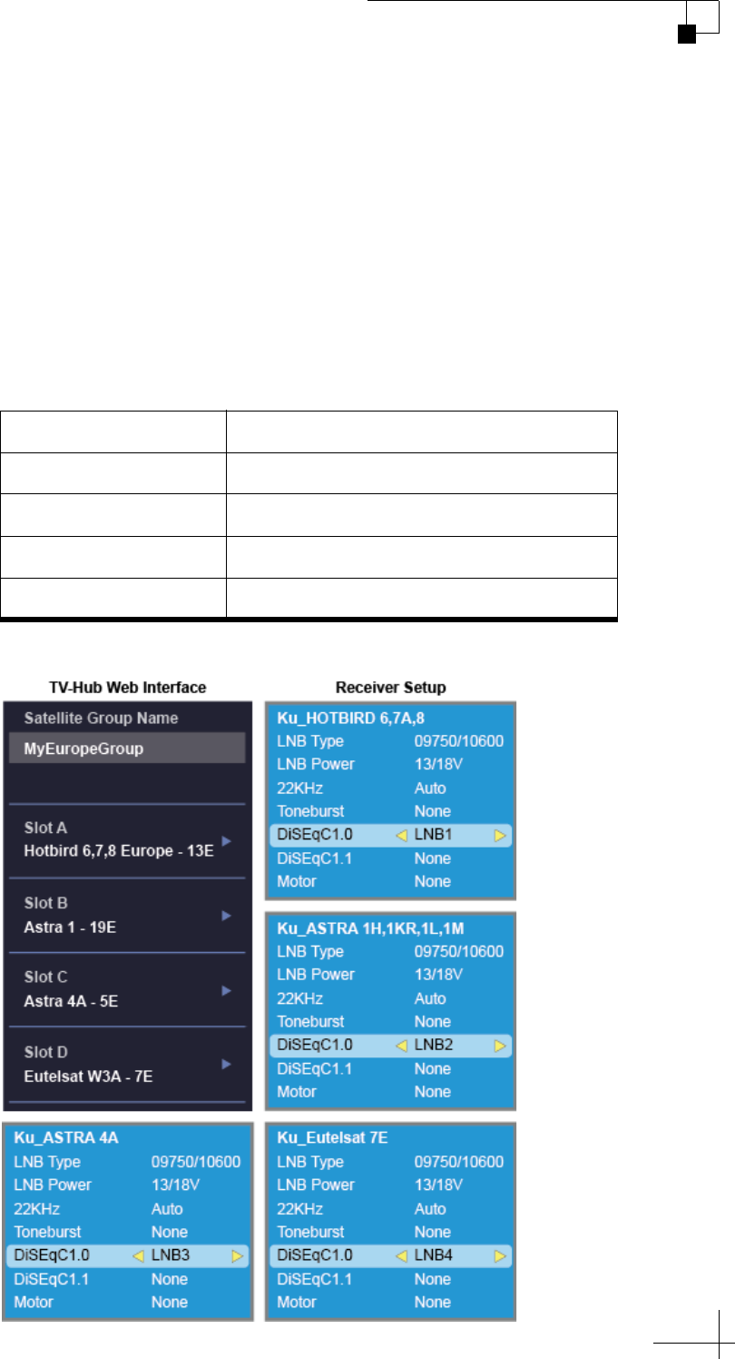
For automatic satellite switching to work properly using the DiSEqC
communication protocol, you need to set up your receivers for the
same satellites you installed in the TracVision antenna. Be sure to set
up the satellites in the receiver in the exact same order as they were set
up in the antenna. The specific setup process varies among receiver
models – refer to your receiver owner’s manual for details. Use the
table and figure below as a guide.
Figure 5-1 Linear Receiver DiSEqC Settings (Example)
Satellites in Antenna Matching Satellites in Receiver
Slot A Port/Switch/LNB/DiSEqC 1 or A
Slot B Port/Switch/LNB/DiSEqC 2 or B
Slot C Port/Switch/LNB/DiSEqC 3 or C
Slot D Port/Switch/LNB/DiSEqC 4 or D
TracVision TV5 User’s Guide
38
Receiver Settings
Configuring DIRECTV Receivers for Automatic
Switching
To establish communications between the TracVision system and each
SWM-compatible DIRECTV receiver for automatic satellite switching,
you need to set each receiver to a static IP address and enter that
address, along with the receiver's location, in the TV-Hub's web
interface. (For details on connecting DIRECTV receivers to the
TracVision system for automatic switching, see “Automatic Satellite
Switching for DIRECTV” on page 69.)
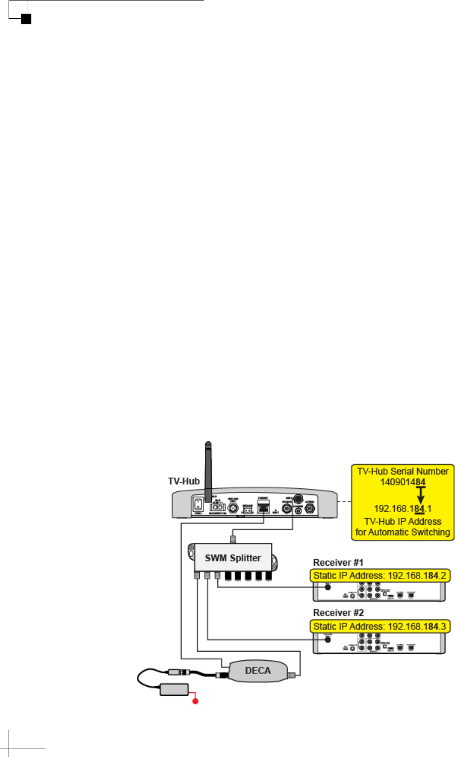
Static IP Address Range WITHOUT an Onboard Network
If the DECA Broadband Kit is connected directly to the TV-Hub's
Ethernet port (no router is installed), set each receiver's IP address to
any address ranging from 192.168.x.2 to 192.168.x.149, where x=1<the
last 2 digits in the TV-Hub’s serial number>.
For example, if the serial number of the TV-Hub is 140901484, you
might assign an IP address of 192.168.184.2. Refer to the instructions in
“Assigning a Static IP Address to a DIRECTV Receiver” on page 40.
The TV-Hub has a hidden IP address of 192.168.x.1 reserved for
automatic switching communications. This IP address is not shown on
the Network Settings page of the web interface.
Figure 5-2 IP Addressing for Automatic Switching (Example)
TracVision TV5 User’s Guide
39
Receiver Settings
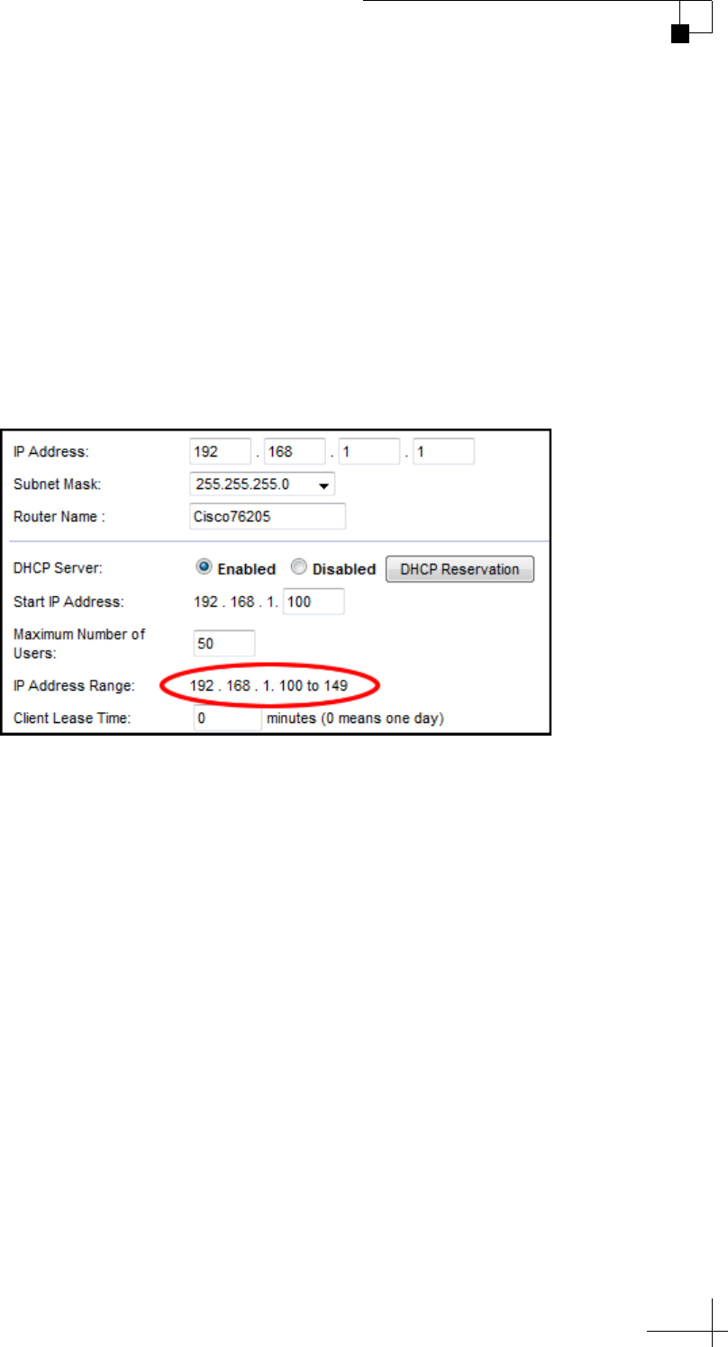
Static IP Address Range WITH an Onboard Network
If the TV-Hub and the DECA Broadband Kit are connected to an
onboard network (i.e., router), set each receiver to a static IP address
that is outside the router's DHCP range. (Refer to your router's user
manual for details on finding its IP address range.) For example, if the
router has an IP address of 192.168.1.1 and assigns IP addresses
ranging from 192.168.1.100 to 192.168.1.149 via DHCP, you could set
each receiver's IP address to any address ranging from 192.168.1.150 to
192.168.1.254. Refer to the instructions in “Assigning a Static IP
Address to a DIRECTV Receiver” on page 40.
Figure 5-3 Router DHCP Settings (Example)

TracVision TV5 User’s Guide
40
Receiver Settings
Assigning a Static IP Address to a DIRECTV Receiver
Once you have identified a valid static IP address range for your
receivers, follow these steps to assign a unique static IP address within
that range to each receiver.
NOTE: These steps may vary, depending on your receiver's model and
software version. Refer to your receiver's owner's manual for details.
NOTE: A video tutorial showing how to navigate to the receiver’s IP address
is available in KVH’s TracVision Tutorials playlist on YouTube (Internet
access required).
1. Activate the receiver for DIRECTV service, if you haven’t
already done so (see “Activating Your Receiver(s)” on
page 48). The receiver must be activated and the antenna
should be tracking the DIRECTV 101W satellite before you can
access the required menus.
2. Press MENU on the receiver's remote control to access the
onscreen menu.
3. At the main menu, highlight Settings & Help. Then select
Settings.
4. Highlight and select Network Setup.
5. Select Advanced Setup.
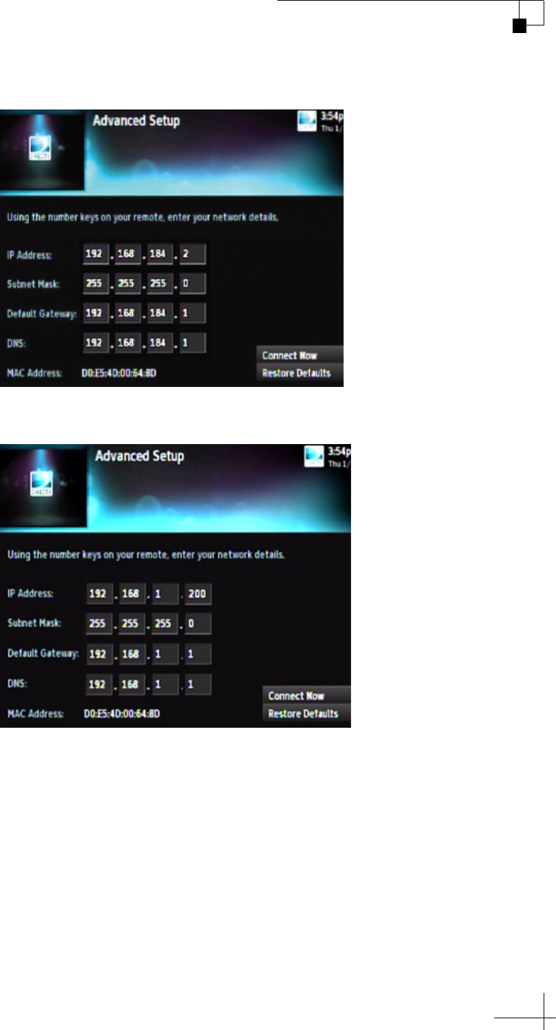
6. Change the IP address to the new static IP address.
7. Without an Onboard Network: Enter “255.255.255.0” for the
subnet mask and enter the TV-Hub’s IP address for default
gateway and DNS.
With an Onboard Network: Enter the router’s subnet mask
and enter the router’s IP address for default gateway and DNS.
8. Highlight and select Connect Now to save your changes.
Disregard any error messages about missing Internet
connectivity. Note this receiver's IP address and location
onboard for future reference.
9. Repeat this procedure for each additional receiver. Be careful
not to use the same IP address twice.
NOTE: For any of the receivers to be the Master Receiver, add the receiver to
the Autoswitch page of the web interface. (For details, see “Automatic
Satellite Switching for DIRECTV” on page 69.)
TracVision TV5 User’s Guide
41
Receiver Settings
Figure 5-4 IP Address on a DIRECTV Receiver WITHOUT an Onboard Network (Example)
Figure 5-5 IP Address on a DIRECTV Receiver WITH an Onboard Network (Example)
TracVision TV5 User’s Guide
42
Receiver Settings
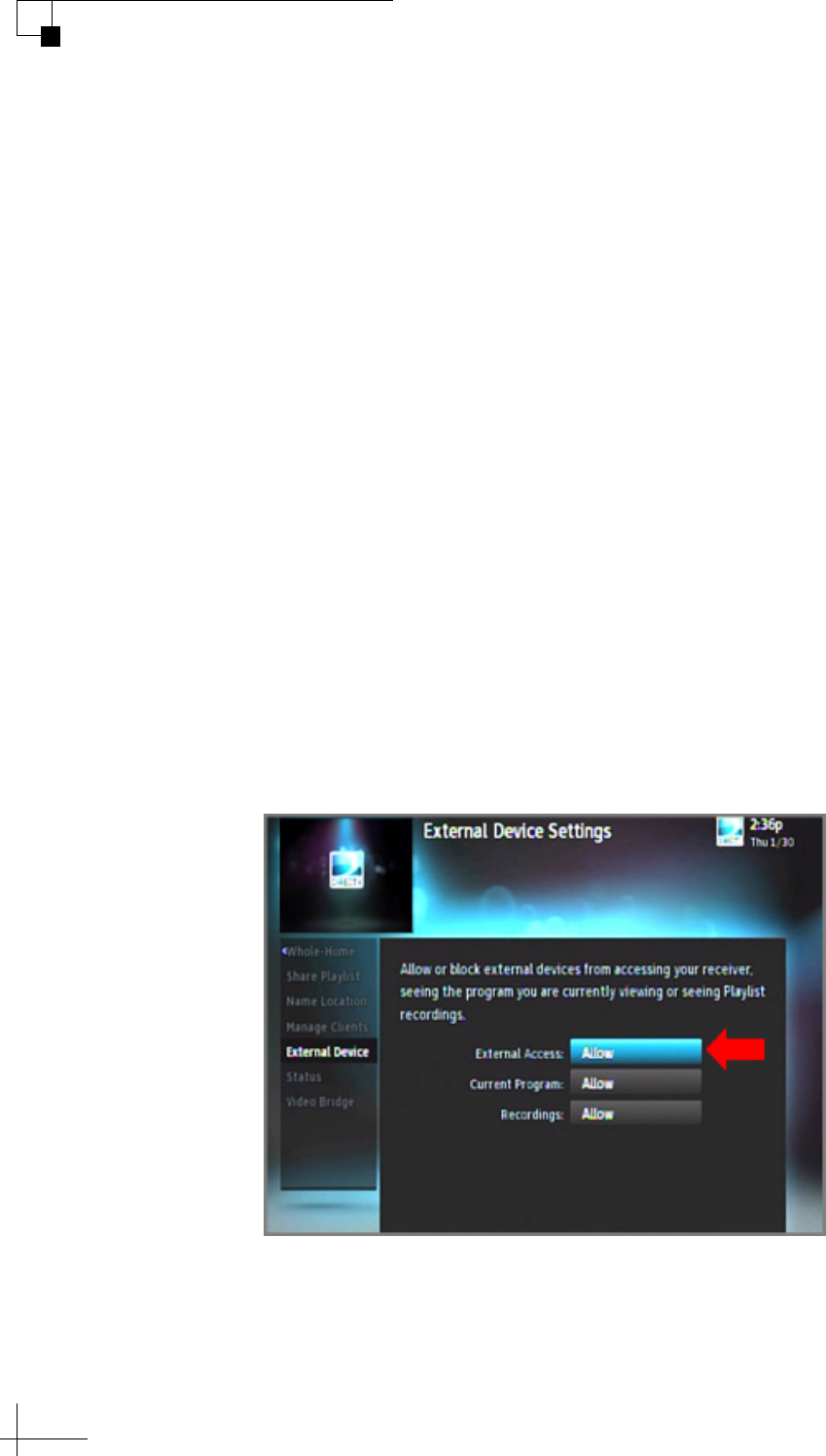
Allowing External Access on a DIRECTV Receiver
For automatic satellite switching, the TV-Hub needs to communicate
with the receiver over the network. The receiver needs to be set up to
allow this external access. To allow external access on a DIRECTV
receiver, follow these steps:
NOTE: A video tutorial of this procedure is available in KVH’s TracVision
Tutorials playlist on YouTube (Internet access required).
1. Press MENU on the receiver’s remote control to access the
onscreen menu.
2. At the main menu, highlight Settings & Help. Then select
Settings.
3. Highlight and select Whole-Home
4. Highlight and select External Device.
5. Set External Access to Allow.
6. At the warning message, select OK.
Figure 5-6 External Device Settings on DIRECTV Receiver
TracVision TV5 User’s Guide
43
Receiver Settings
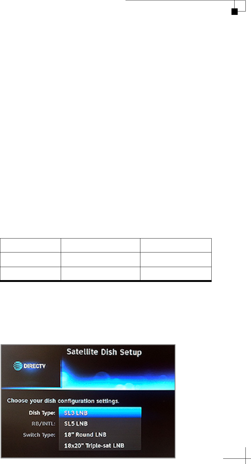
Setting the Dish Type on a DIRECTV Receiver
To work with the TracVision system, the DIRECTV SWM receiver(s)
must be set to the correct dish type for your particular configuration.
To set or verify the dish type, follow these steps:
1. Press MENU on the receiver’s remote control to access the
onscreen menu.
2. At the main menu, highlight Settings & Help. Then select
Settings.
3. Highlight and select Satellite.
4. Highlight and select Repeat Satellite Setup.
5. At the warning message, press the Dash (-) button on the
receiver’s remote control.
6. Make sure your receiver is set to the appropriate dish type for
the satellite(s) you need:
* The 119 satellite carries just local channels for certain regions of the
U.S. See www.kvh.com/dtv119locals for the latest list.
7. Highlight and select Continue to save your changes.
Figure 5-7 Dish Type Menu on DIRECTV Receiver (Example)
Satellite(s)* Dish Type Switch Type
101W only 18" Round LNB SWM Module 8 CH
101W and 119W 18x20" Triple-sat LNB SWM Module 8 CH

TracVision TV5 User’s Guide
44
Receiver Settings
Running a Check Switch Test on a DISH Network
or Bell TV Receiver
To operate with the TracVision system, you need to run a single Check
Switch test on every DISH Network or Bell TV receiver. To run a
Check Switch test, follow these steps:
NOTE: A video tutorial of this procedure is available in KVH’s TracVision
Tutorials playlist on YouTube (Internet access required).
1. Make sure the vessel is docked in calm water in a blockage-free
area. The antenna must have an unobstructed view of the sky.
2. Connect the receiver directly to the “Receiver” port on the back
of the TV-Hub. You must run the Check Switch test on each
receiver, one at a time, while it is connected directly to the
TV-Hub via a single RF coax cable.
3. Turn on the TracVision system and connect to the web
interface (see “Accessing the Web Interface” on page 14).
Proceed through the steps of the Setup Wizard until it prompts
you to run the Check Switch test. If the Setup Wizard does not
display automatically, you can launch the Setup Wizard from
the web interface (go to Settings > General Settings).
4. Connect a TV to the receiver so you can view the receiver’s
onscreen menu.
NOTE: The setup process may differ depending on service provider and
receiver model. Refer to your receiver owner’s manual for details. For a Wally,
refer to “Running a Check Switch Test on a Wally Receiver” on page 46.
5. At the Program Remote to Receiver screen, press SAT then
RECORD on the receiver’s remote to begin the setup process.
Important!
The antenna must remain motionless throughout this procedure.
Important!
If the Program Remote to Receiver screen does not appear, or the
screen shows “Acquiring Signal,” go to the Point Dish screen by
pressing MENU, 6, 1, 1 on the receiver’s remote. Then perform steps 11
and 12 of this procedure to run a Check Switch test. In the case of the
“Acquiring Signal” screen, you need to press MENU, 6, 1, 1 while that
screen is displayed. Otherwise, you will need to reset the receiver and retry.
TracVision TV5 User’s Guide
45
Receiver Settings
6. When the number for your remote control appears on the
screen, select Continue.
7. Wait while the receiver downloads the latest software. This
update may take up to 20 minutes.
8. At the Set Video Resolution screen, select the highest video
resolution that is supported by your TV. Then run the
resolution test and save your setting.
9. Allow the receiver to run two tests of its landline connections
(Ethernet and phone). It probably won’t detect any, since the
receiver is installed in a mobile environment.
10. At the Activate Receiver screen, press STAR (*) on the
receiver’s remote.
11. At the Setup Details screen, select Point Dish. Then select
Check Switch. The receiver now runs the Check Switch test.
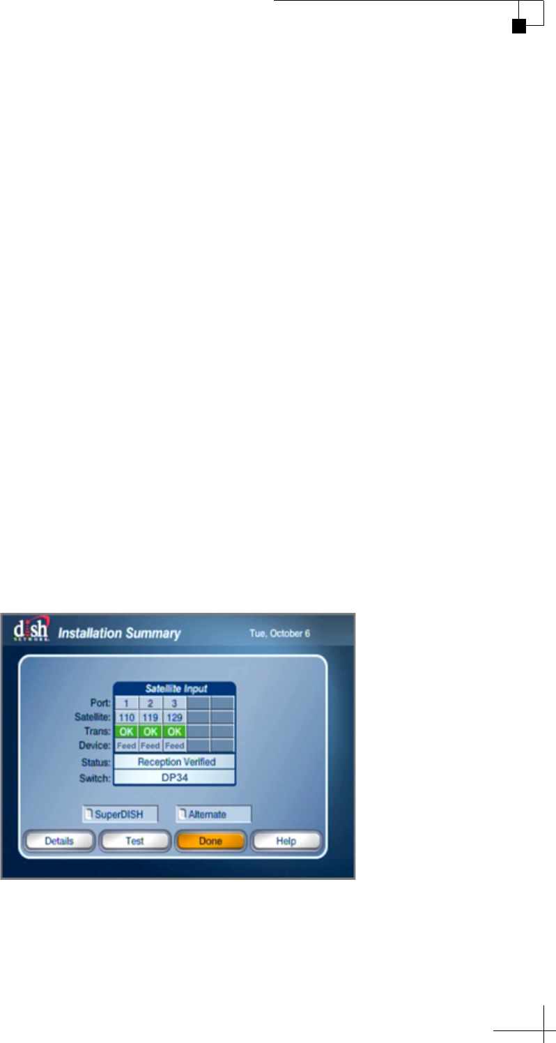
12. At the Installation Summary screen, make sure all of the
satellites you installed in the TracVision antenna are listed
“OK.” Also be sure the switch type is “DP34.” If you do not see
these results, select Test to run another test. Otherwise, select
Done.
Figure 5-8 Check Switch Test Results
13. At the Point Dish screen, select Done.
14. At the Setup Details screen, select Continue.
15. Allow the receiver to run two additional tests of its landline
connections.
TracVision TV5 User’s Guide
46
Receiver Settings
16. At this point, you may activate the receiver. Call the number
provided in “Activating Your Receiver(s)” on page 48. Once
the receiver is activated, the process is complete.
17. Repeat this procedure for any additional receivers, making
sure you connect each receiver directly to the TV-Hub as
directed in step 2. When you are done, reconnect all system
components as necessary for your chosen configuration.
18. When you are done running Check Switch tests, proceed to the
next page of the Setup Wizard. Do not close your web browser
window to exit.
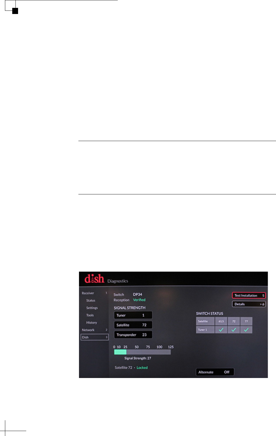
Running a Check Switch Test on a Wally Receiver
The menu on the Wally receiver differs from other models. To run a
Check Switch test on a Wally, go to Settings > Diagnostics > Dish.
Then select Test Installation. When the test is complete, make sure all
the satellites are listed with a check mark and the switch is “DP34.”
Figure 5-9 Check Switch Test Results on a Wally
Important!
If you accidentally close your web browser window instead of
proceeding to the next page of the Setup Wizard, be sure to set the
Check Switch mode to Off at the General Settings page of the web
interface. See “Check Switch Mode” on page 47 for details.

TracVision TV5 User’s Guide
47
Receiver Settings
Check Switch Mode
When the Setup Wizard prompts you to run a Check Switch test for a
DISH Network or Bell TV configuration, the antenna automatically
enables Check Switch mode. In this mode, the antenna stops actively
tracking and stores the relative pointing position to each installed
satellite. Satellite switching is nearly instantaneous - the antenna just
shifts to the stored pointing positions. This rapid switching allows a
Check Switch test to pass on its first attempt. (The receiver assumes it
is connected to a stationary home antenna with multiple LNBs, so it
expects all satellites to be available at once.)
Keep the Check Switch mode set to Off (default setting) for normal
operation. Check Switch mode should only be set to On when you
need to run a Check Switch test on a receiver. You can change the
current Check Switch mode setting at the web interface (go to Settings
> General Settings).
Important!
While in Check Switch mode, the antenna must remain motionless.
Since the antenna is not tracking the satellite in this mode, any
movement will throw off the relative pointing positions.

TracVision TV5 User’s Guide
48
Receiver Settings
Activating Your Receiver(s)
Before you can watch television, the receiver(s) must be activated for
your satellite TV service. Refer to the receiver owner’s manual or
packaging for details.
To activate DIRECTV U.S. or DISH Network receivers, call the
following:
To activate: Call:
DIRECTV U.S. +1 866 551-8004
DISH Network +1 800 970-9829

TracVision TV5 User’s Guide
49
Satellite Settings
6. Satellite Settings
This section explains how to select, edit, and add satellites and satellite
groups.
Contents
Selecting a Single Satellite.............................................. 51
Creating a New Satellite.................................................. 52
Selecting a Satellite Group .............................................. 53
Creating a New Satellite Group ....................................... 58
Changing Satellites in a Group ........................................ 60
Changing Satellite Tracking Parameters ......................... 61
TracVision TV5 User’s Guide
51
Satellite Settings
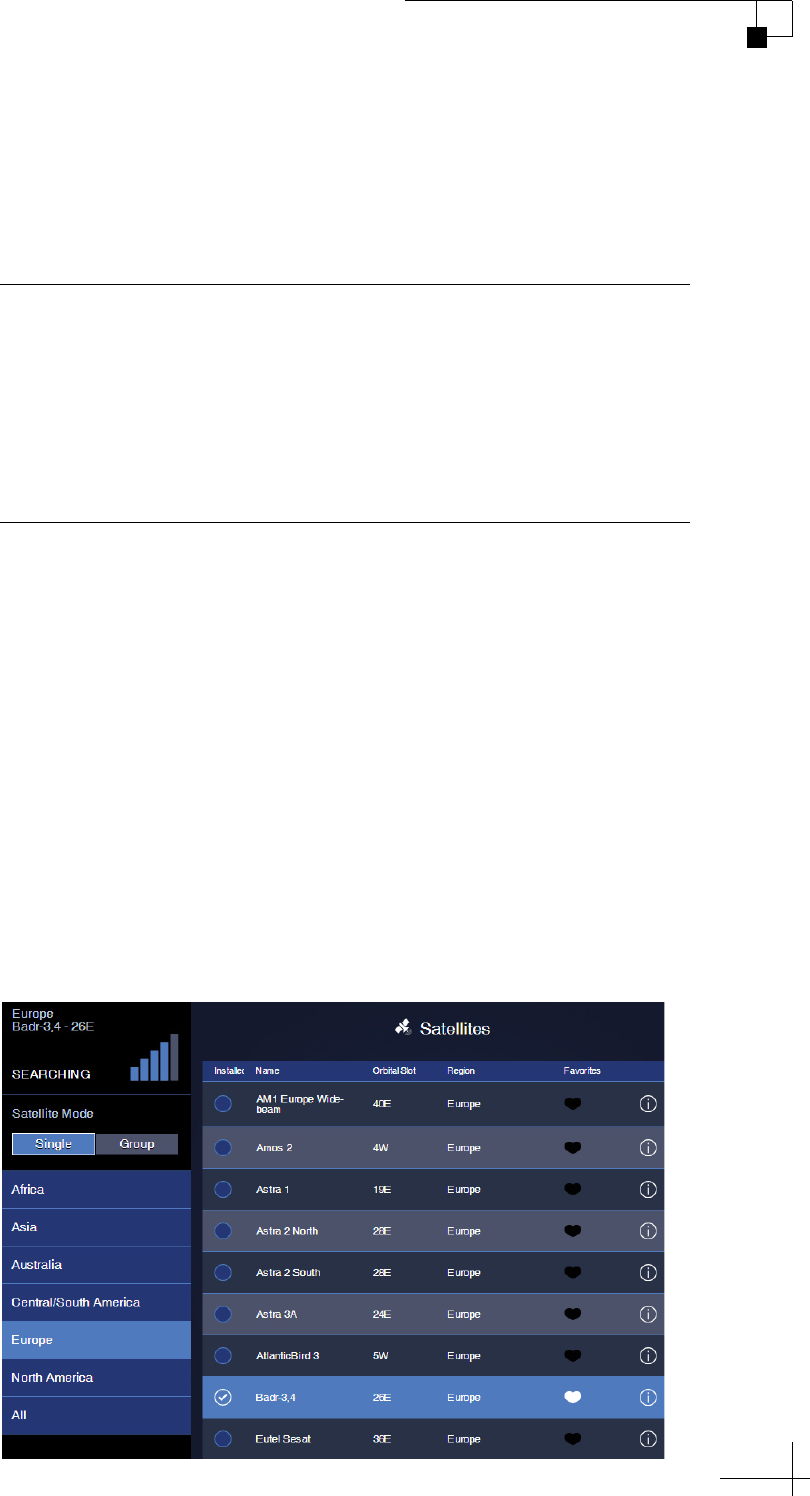
Selecting a Single Satellite
If all of the programming you want to watch is carried by a single
satellite, follow these steps to configure the antenna to track that one
satellite:
1. On the Satellites page of the web interface, set Satellite Mode to
Single.
2. All satellites that are compatible with your antenna and its
currently installed LNB are displayed in a list. Choose a region
to filter the list for your location (e.g., Europe). You can also
order the list by name, orbital slot, or region by clicking the
associated header.
3. Find the desired satellite and select Installed. The antenna will
start searching for the selected satellite.
NOTE: If the satellite you want to track is missing, you can add it to the list.
See “Creating a New Satellite” on page 52 for details.
Figure 6-1 Single Satellite Mode
Important!
KVH recommends that you run the Setup Wizard whenever you need
to change the configuration of your system (especially if you need to
change your satellite TV service or receiver equipment). The Wizard
will guide you through all of the necessary configuration steps,
including satellite selection. You can launch the Setup Wizard from the
web interface (go to Settings > General Settings).
TracVision TV5 User’s Guide
52
Satellite Settings
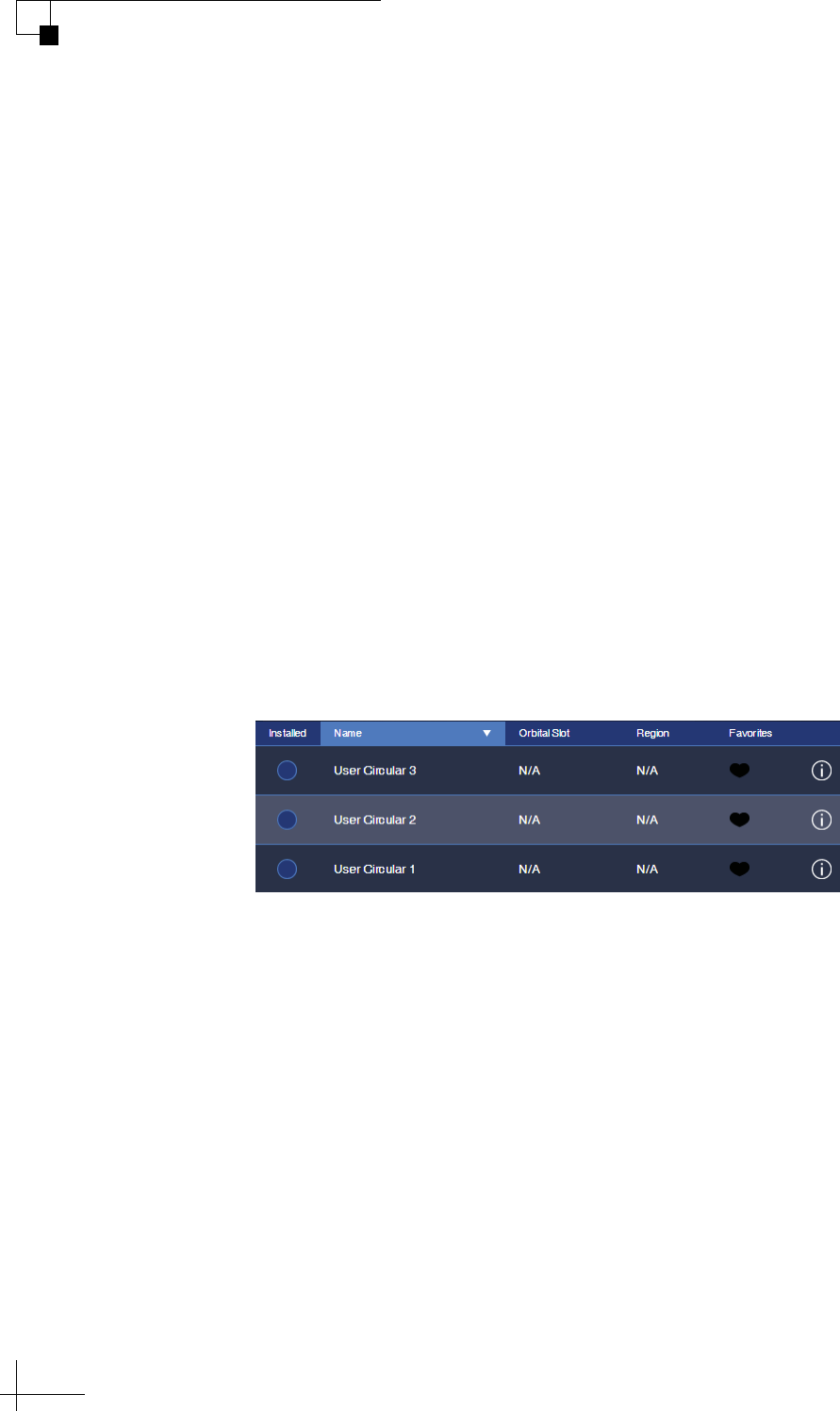
Creating a New Satellite
If the satellite you wish to track is not included in the satellite library,
you can add a new custom “User” satellite. To create a new satellite,
follow these steps:
1. On the Satellites page of the web interface, click the (i)
information icon next to any of the “User” satellites.
2. Fill in all of the tracking parameters with the correct
information for your desired satellite. See “Changing Satellite
Tracking Parameters” on page 61.
NOTE: You can only create a satellite that is compatible with the LNB that is
currently installed in the antenna (i.e. Circular or Linear).
3. Choose a friendly name for your new satellite, so that you can
easily identify it later. Then save your changes.
4. To install your new satellite in the antenna for tracking, follow
the steps in “Selecting a Single Satellite” on page 51.
Figure 6-2 User Satellites (Circular)
TracVision TV5 User’s Guide
53
Satellite Settings
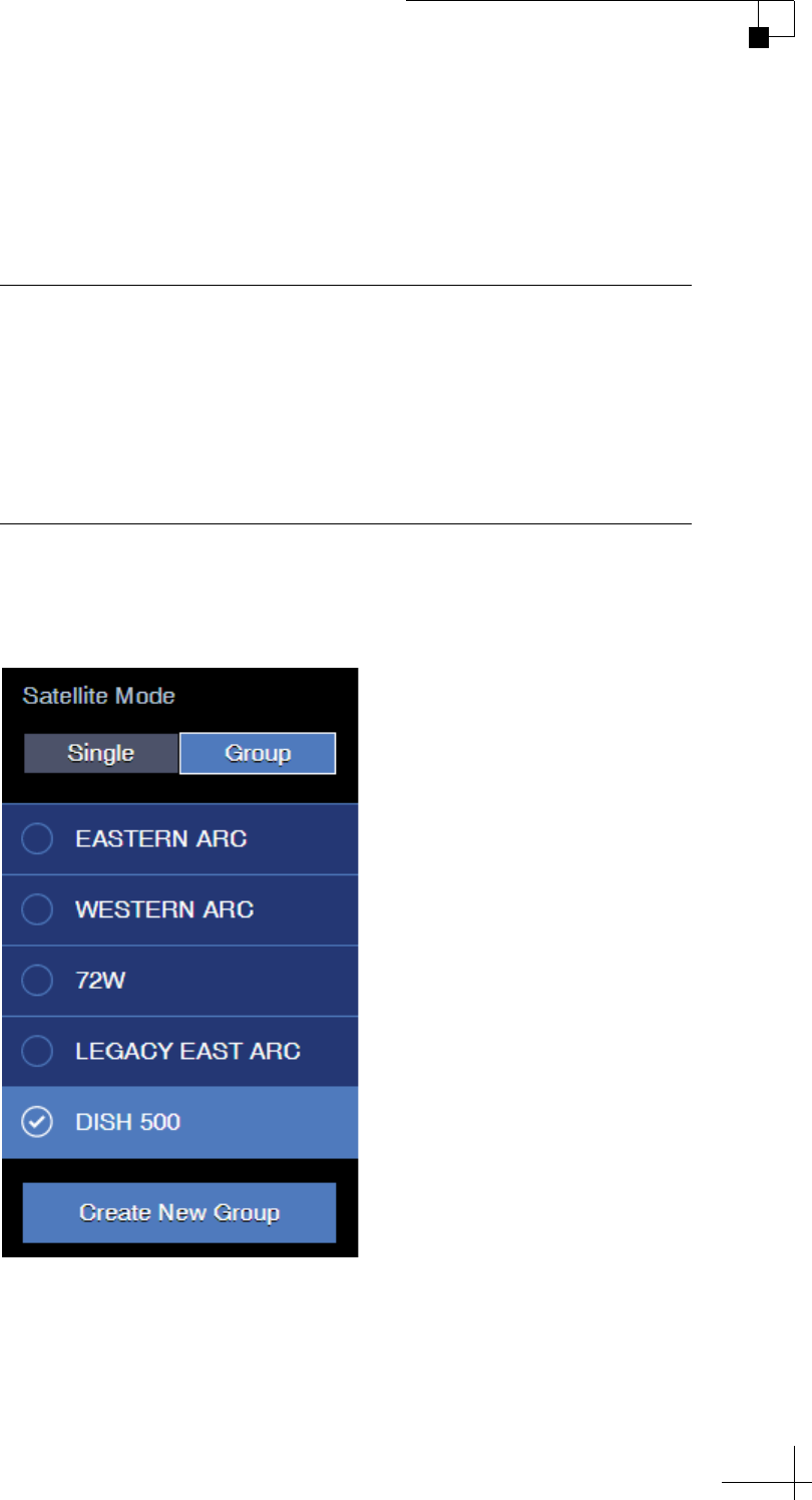
Selecting a Satellite Group
The TV-Hub comes preloaded with some of the most popular groups
of satellites. To select one of these preset groups for tracking, or to
select a custom group that you created yourself, follow these steps:
1. On the Satellites page of the web interface, set Satellite Mode to
Group.
Figure 6-3 Preset Satellite Groups (Example)
2. Choose a satellite group from the list. (This list will vary
depending on your system’s configuration.) All preset groups
are listed below.
Important!
KVH recommends that you run the Setup Wizard whenever you need
to change the configuration of your system (especially if you need to
change your satellite TV service or receiver equipment). The Wizard
will guide you through all of the necessary configuration steps,
including satellite selection. You can launch the Setup Wizard from the
web interface (go to Settings > General Settings).
TracVision TV5 User’s Guide
54
Satellite Settings
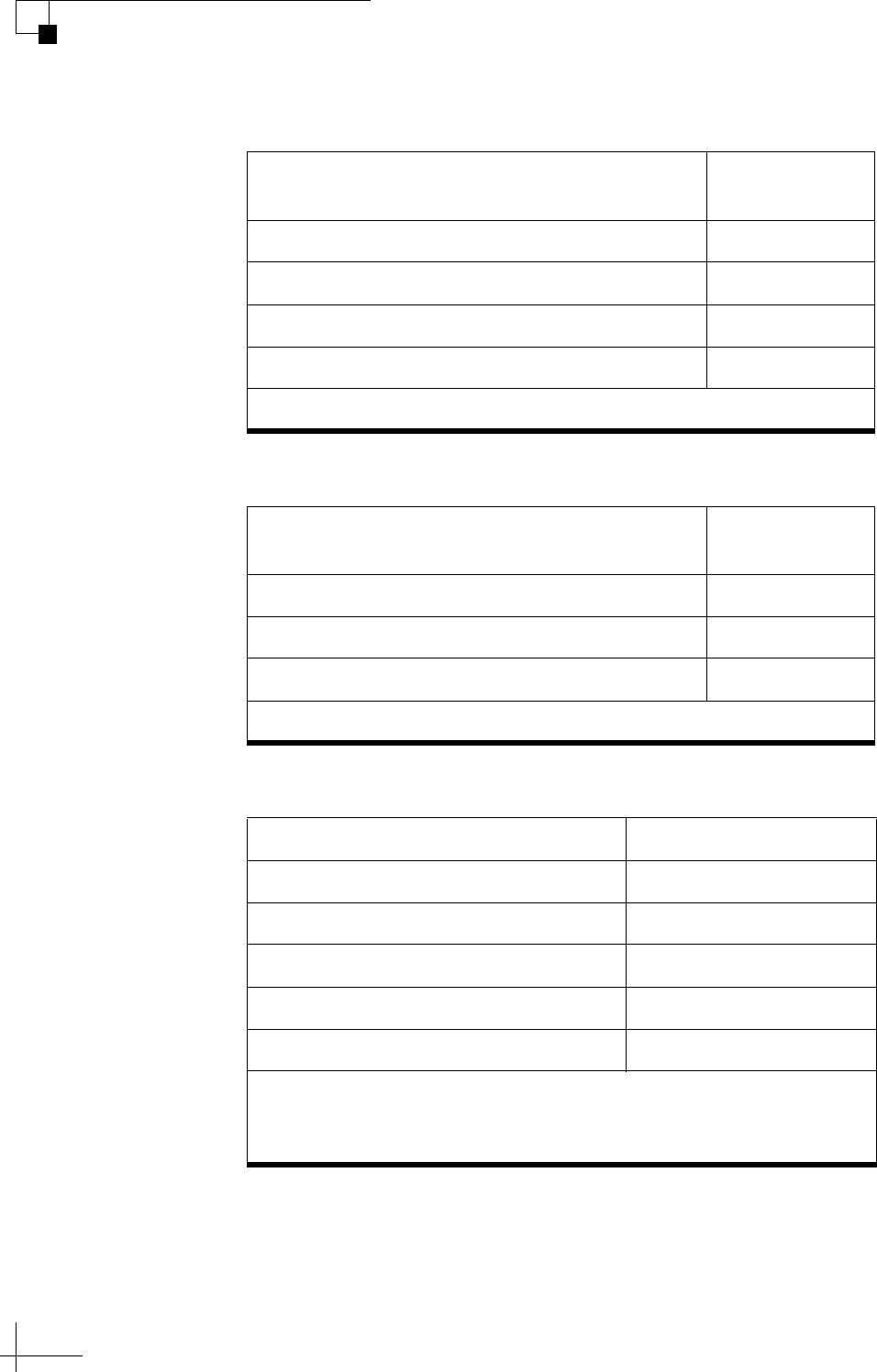
Linear Groups
DIRECTV Groups
DISH Network Groups
Preset Satellite Groups (A–B–C–D)
Compatible
Antennas
Europe 1: Hotbird – Astra1 – Astra2S – Astra3 TV5, TV6, TV8*
Europe 2: Astra3 – Astra1 – Hotbird – Astra2S TV5, TV6, TV8*
Scandinavia: Astra4 – Thor – Hotbird – Astra1 TV5, TV6, TV8*
Holland 1: Astra1 (Holland) – Astra3 (Holland) TV5, TV6, TV8*
* Automatic skew required.
Preset Satellite Groups
Compatible
Antennas
DIRECTV Dual: 101W – 119W All
Tri-Am TriSat: 101W – 119W – 95W TV5, TV6, TV8*
Tri-Am Dual: 101W – 95W TV5, TV6, TV8*
* Tri-Americas LNB required (DIRECTV U.S. + Latin America).
Preset Satellite Groups Compatible Antennas
Eastern Arc: 61W – 72W – 77W A9, TV3, TV5, TV6, TV8*
Western Arc: 110W – 119W – 129W All*
Legacy East Arc: 61W – 110W – 119W All*
DISH 500: 110W – 119W All*
72W: 72W only A9, TV3, TV5, TV6, TV8*
* TV1/RV1 is not compatible with the Eastern Arc or 72W at this time. In
addition, the TV1/RV1/A9 cannot see all DISH Network satellites from all
locations in the U.S. (see “Satellite Elevation Limitations” on page 55).
TracVision TV5 User’s Guide
55
Satellite Settings
Bell TV Group
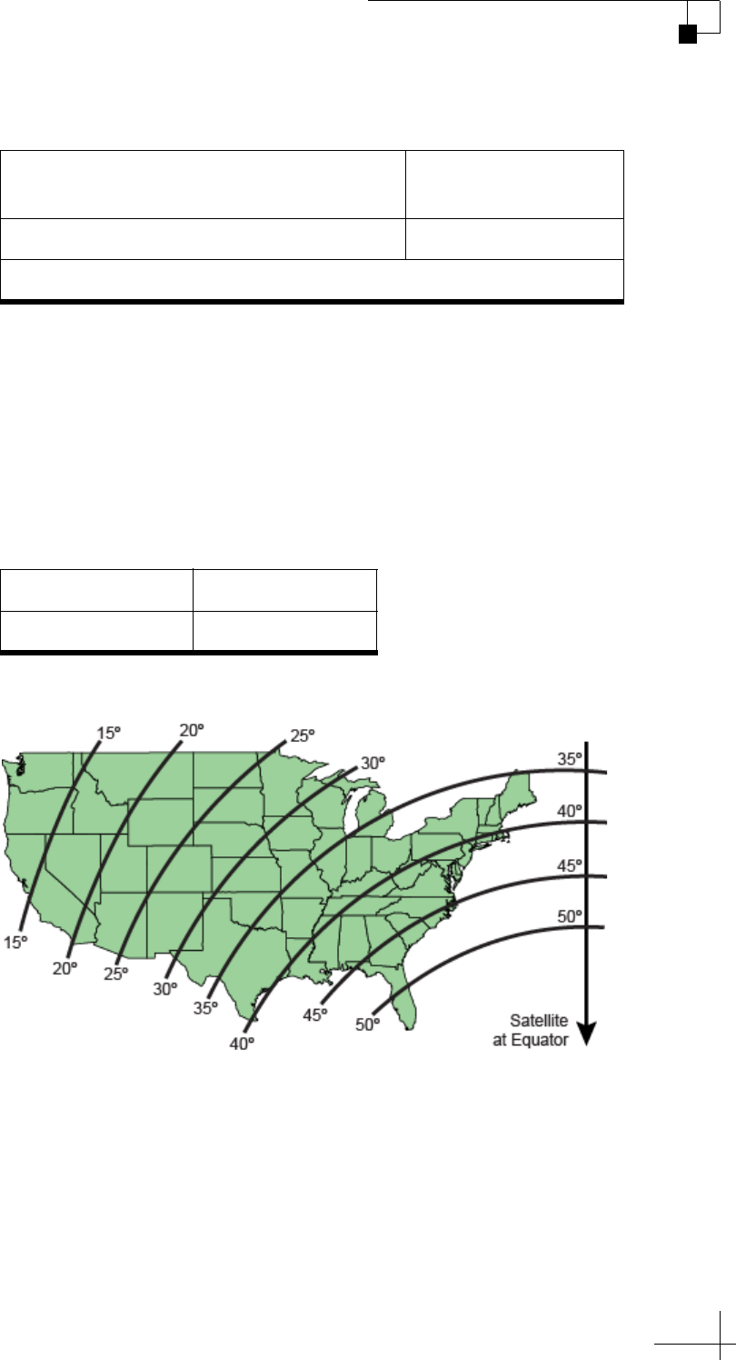
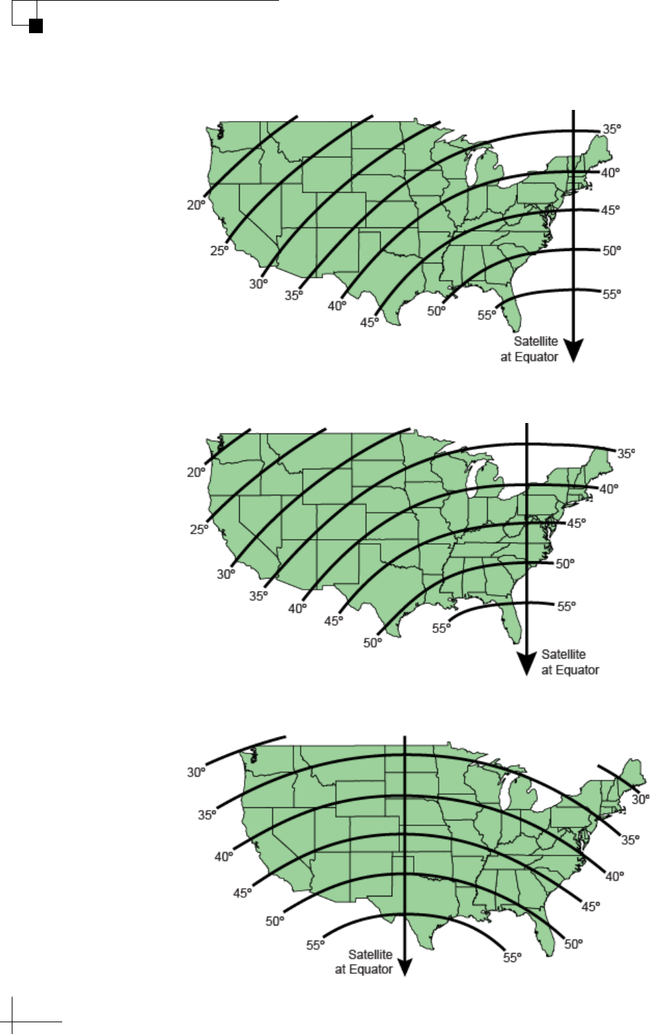
Satellite Elevation Limitations
The antenna must point directly at the satellite to receive its TV
signals. The elevation at which the antenna must point depends on
your current position and the longitude (or orbital slot) of the selected
satellite. In general, the closer you get to the satellite at the equator, the
higher the elevation. Conversely, the farther away you are, the lower
the elevation. In both cases, the antenna won’t be able to see the
satellite if its elevation exceeds the antenna’s range.
Figure 6-4 Approximate Elevations to the 61W Satellite
Preset Satellite Group
Compatible
Antennas
Bell TV Dual: 82W – 91W TV3, TV5, TV6, TV8*
* TV1/RV1 is limited to the 91W satellite at this time.
Antenna Model Elevation Range
TV5 0º-80º
TracVision TV5 User’s Guide
56
Satellite Settings
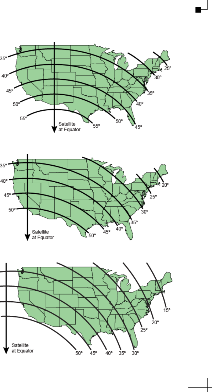
Figure 6-5 Approximate Elevations to the 72W Satellite
Figure 6-6 Approximate Elevations to the 77W Satellite
Figure 6-7 Approximate Elevations to the 101W Satellite
TracVision TV5 User’s Guide
57
Satellite Settings
Figure 6-8 Approximate Elevations to the 110W Satellite
Figure 6-9 Approximate Elevations to the 119W Satellite
Figure 6-10 Approximate Elevations to the 129W Satellite

TracVision TV5 User’s Guide
58
Satellite Settings
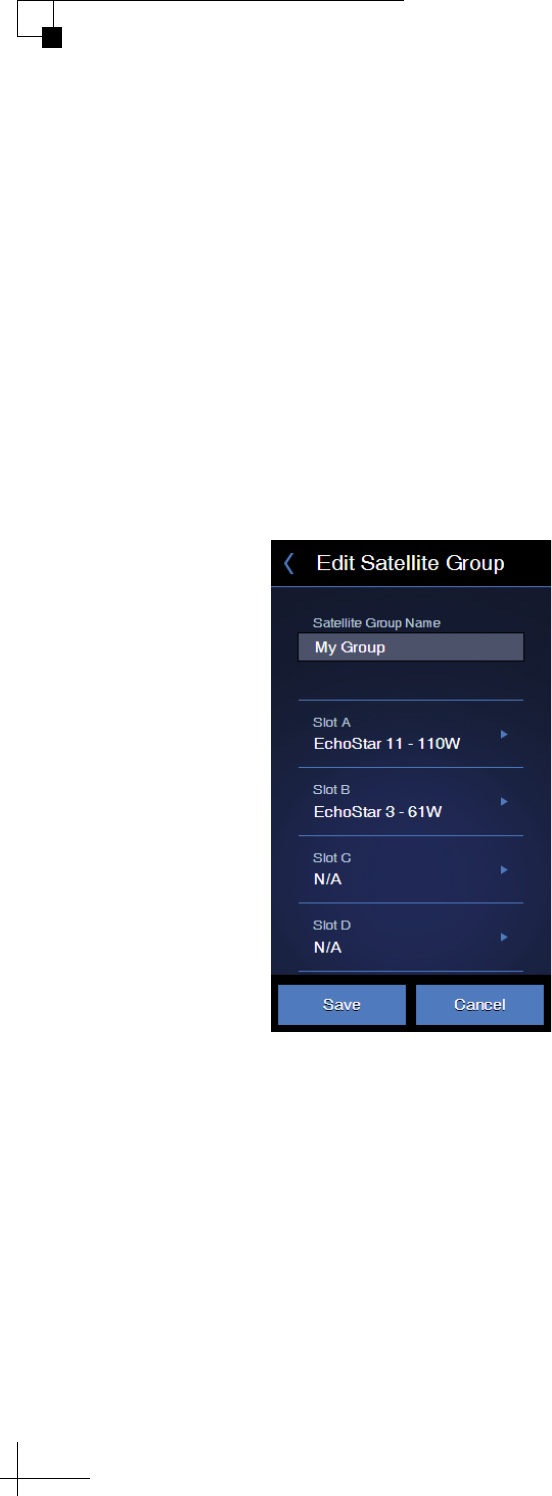
Creating a New Satellite Group
If there is no preset satellite group containing the satellites you want to
track, you can create your own custom satellite group. Follow these
steps:
1. On the Satellites page of the web interface, set Satellite Mode to
Group.
2. Select Create New Group.
3. Choose up to four satellites from the satellite library to include
in your new satellite group.
4. Choose a friendly name for your group, so that you can easily
identify it later. Then save your changes.
5. To install the new satellite group in the antenna for tracking,
follow the steps in “Selecting a Satellite Group” on page 53.
NOTE: If you assign your new group the same name as an existing user-
defined group, the new group will overwrite the older one. You cannot use
any of the names that are reserved for preset groups.
Important!
When adding linear satellites to a group, be sure to consider the skew
angle for each satellite if the antenna is not equipped with automatic
skew. In general, if the satellites are greater than 10° apart in longitude,
you will not be able to set the LNB at a skew angle that works for all of
them. You might need to adjust the skew whenever you switch
satellites.
TracVision TV5 User’s Guide
59
Satellite Settings
Figure 6-11 Creating a New Satellite Group
TracVision TV5 User’s Guide
60
Satellite Settings
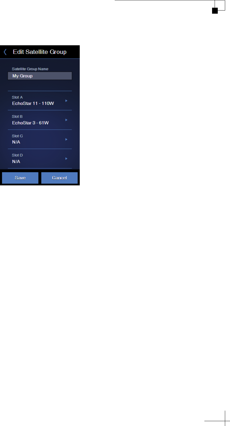
Changing Satellites in a Group
While you cannot alter the satellites in a preset group, you can change
the satellites that are included in any user-defined group. Follow these
steps to edit a user-defined group:
1. On the Satellites page of the web interface, set Satellite Mode to
Group.
2. Select the group you want to modify, then select Edit Group.
3. Change any of the four satellites you want to replace. Then
save your changes.
Figure 6-12 Editing a Satellite Group

TracVision TV5 User’s Guide
61
Satellite Settings
Changing Satellite Tracking Parameters
A satellite TV service provider may change a transponder frequency or
other satellite parameters at any time without warning. Since the
antenna uses these parameters to identify and track the satellite, the
TV-Hub allows you to change the tracking parameters of any satellite
in its library.
NOTE: KVH regularly updates the satellite library for service provider
changes. You can download the latest update from the TV-Hub web interface.
See “Updating the Satellite Library” on page 104 for details. Your local KVH
dealer or distributor will be informed whenever an update is required.
NOTE: You can find satellite information on the web at www.lyngsat.com
(not affiliated with KVH).
To manually edit the tracking parameters of a satellite, follow these
steps:
1. On the Satellites page of the web interface, click the (i)
information icon next to the affected satellite.
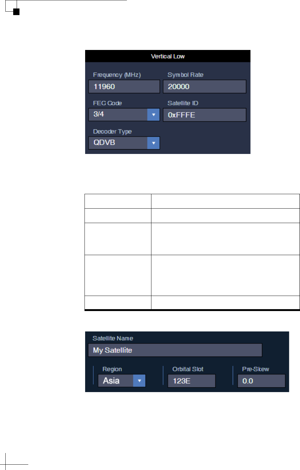
2. Make the necessary changes to the tracking parameters. Then
save your changes.
Be sure to set the parameters for each polarization/band. Linear
satellites use four combinations of polarization/band: Horizontal
Low, Horizontal High, Vertical Low, and Vertical High. Circular
satellites use two polarizations in a single band: Right and Left.
Editable tracking parameters for any satellite are listed below.
Parameter Description
Frequency 00000 MHz or 10700 MHz-12750 MHz
Symbol Rate 1000-45000 (33000 max if DVB-S2)
FEC Code 1/2, 2/3, 3/4, 3/5, 4/5, 5/6, 5/11, 6/7, 7/8,
8/9, 9/9, or 9/10
Satellite ID Hexadecimal (0x####)
Decoder Type QDSS: Legacy DSS
QDC2: Digicipher II QPSK
QDVB: Legacy DVB
LQPSK: DVB-S2 QPSK
L8PSK: DVB-S2 8PSK
TQPSK: Turbo QPSK
T8PSK: Turbo 8PSK
TracVision TV5 User’s Guide
62
Satellite Settings
Figure 6-13 Edit Satellite Details
3. If the satellite is a custom user-defined satellite, you can change
the additional parameters listed below.
Figure 6-14 Additional Parameters for User-defined Satellite
NOTE: LNB type and local oscillator frequencies cannot be modified, as they
are properties of the LNB installed in the antenna.
Parameter Description
Satellite Name User-defined name (e.g., User Sat 1)
Region Africa, Asia, Australia/New Zealand,
Central/South America, Europe, or North
America
Orbital Slot
(Longitude)
Longitude of the satellite’s position, using the
following format: xxx.xxE or xxx.xxW
(leading zeros and decimal values are
optional)
Pre-Skew -90° to +90°

TracVision TV5 User’s Guide
63
Switching Satellites
7. Switching Satellites
This section explains how to switch between multiple satellites installed
in the antenna.
Contents
Automatic Satellite Switching for Linear, DISH Network, or Bell TV................65
Automatic Satellite Switching for DIRECTV .....................................................69
Selecting Automatic Switching Mode..............................................................76
Selecting the Master Receiver ........................................................................77
Manual Satellite Switching..............................................................................78
Tri-Americas Satellite Switching.....................................................................79
TracVision TV5 User’s Guide
65
Switching Satellites
Automatic Satellite Switching for Linear, DISH
Network, or Bell TV
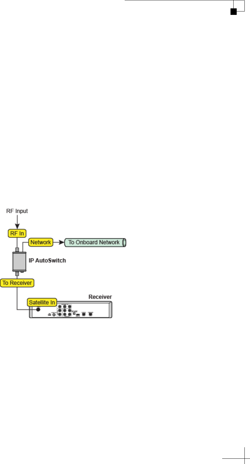
In Automatic satellite switching mode, the TV-Hub can accept DiSEqC
satellite change commands from linear, DISH Network, or Bell TV
receivers that are either:
• Connected directly to the TV-Hub’s “Receiver” port
• Equipped with an IP AutoSwitch
IP AutoSwitches send DiSEqC commands via your onboard local area
network (LAN). See “Network Settings” on page 15 for network setup
details.
NOTE: An IP AutoSwitch is not required for a receiver connected directly to
the TV-Hub because the TV-Hub has a built-in IP AutoSwitch.
Figure 7-1 IP AutoSwitch Connections
Each receiver and IP AutoSwitch needs to be set up for automatic
switching, as explained in the following topics:
• “Setting Up a Linear Receiver for Automatic Switching” on
page 66
• “Setting Up a DISH Network/Bell TV Receiver for
Automatic Switching” on page 67
• “Setting Up an IP AutoSwitch” on page 68

TracVision TV5 User’s Guide
66
Switching Satellites
Setting Up a Linear Receiver for Automatic Switching
For automatic switching to work properly with your linear receivers,
be sure to set up the satellites in each receiver in the same order as they
are set up in the antenna. See “Configuring a Linear Receiver for
Automatic Switching” on page 37 for details.

TracVision TV5 User’s Guide
67
Switching Satellites
Setting Up a DISH Network/Bell TV Receiver for Automatic Switching
For automatic switching to work properly with your DISH Network or
Bell TV receivers, be sure to observe the following requirements:
• Make sure each receiver is DISH pro-compatible. Look for
the DISH Pro logo on the box.
• Select a preset satellite group (see “Selecting a Satellite
Group” on page 53). User-defined groups are limited to
manual satellite switching only.
• Run the TracVision Setup Wizard and initiate a Check
Switch test on the receiver when prompted to do so. See
“Running a Check Switch Test on a DISH Network or Bell
TV Receiver” on page 44 for details. You can launch the
Setup Wizard from the web interface (go to Settings >
General Settings).
NOTE: In some cases, a DISH Network receiver might automatically switch
from a high-definition (HD) channel to its standard-definition (SD)
equivalent. To prevent this from happening, always tune to the HD-only
channels at the upper range of the channel list (above 1000), or set up the
receiver to block the SD channels (from the Main Menu, select Locks:5 >
Channel Locks:2).

TracVision TV5 User’s Guide
68
Switching Satellites
Setting Up an IP AutoSwitch
Whenever you install a new IP AutoSwitch, you need to add it to the
Autoswitch page of the web interface. Enter the IP AutoSwitch’s serial
number and assign it a friendly name (e.g., “Salon”). You can find the
serial number on the bottom of the IP AutoSwitch.
Figure 7-2 Adding an IP AutoSwitch to the Autoswitch Page

TracVision TV5 User’s Guide
69
Switching Satellites
Automatic Satellite Switching for DIRECTV
In Automatic satellite switching mode, the TV-Hub can accept
commands from the master SWM-compatible DIRECTV receiver to
automatically switch between the 101W and 119W satellites. (To learn
more about SWM technology, see “Understanding DIRECTV SWM
Technology” on page 74.) The TV-Hub communicates with the master
receiver via the TV-Hub’s Ethernet port link to your DIRECTV coax
network. Set up this communication link with your SWM-compatible
receivers, as explained in the following topics:
• “DIRECTV Coax Network Connections” on page 70
• “Additional Equipment for Old DIRECTV Receivers” on
page 71
• “Setting Up a DIRECTV Receiver for Automatic Switching”
on page 73
NOTE: The 119W satellite only carries local channels for certain regions of
the country. (You can find a list of these regions in the Setup Wizard and on
the web at www.kvh.com/dtv119locals.) If your locals are carried on
DIRECTV’s main 101W satellite, you do not need to switch satellites.
TracVision TV5 User’s Guide
70
Switching Satellites
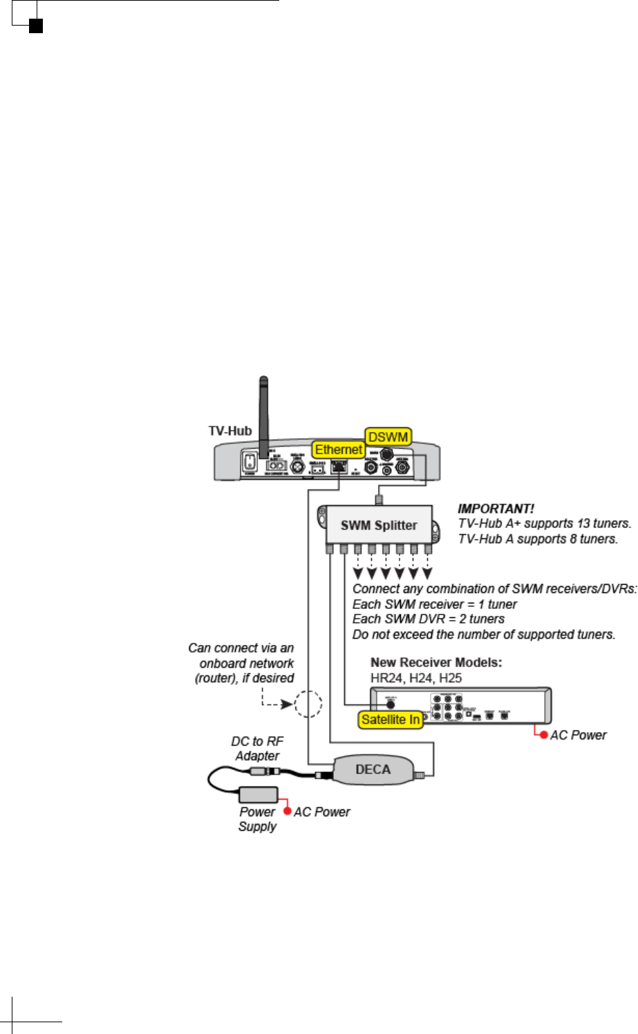
DIRECTV Coax Network Connections
DIRECTV uses coax networking technology, by which both satellite
TV signals and network communications data are carried by the coax
cables. This simplifies installation, since Ethernet cables don't need to
be run to all of the receivers.
Install a DECA with power supply and DC to RF adapter, collectively
referred to as a DECA Broadband Kit (KVH part no. 19-0860) and
formerly called a Cinema Connection Kit. When connected to the
SWM splitter and the TV-Hub's Ethernet port, either directly or via an
onboard router, the DECA relays messages between the DIRECTV
coax network and the Ethernet network.
Figure 7-3 DIRECTV Coax Configuration
TracVision TV5 User’s Guide
71
Switching Satellites
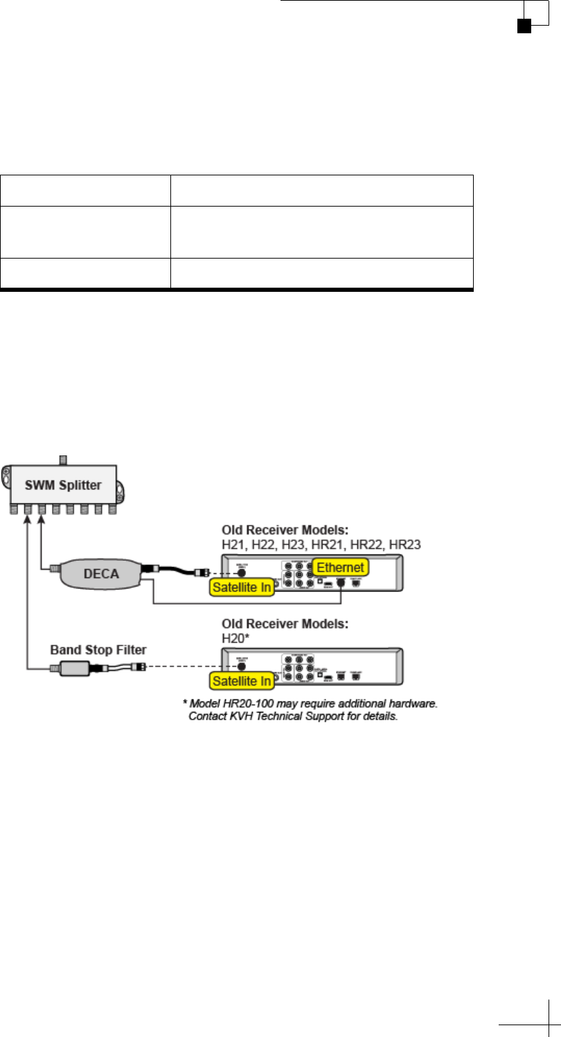
Additional Equipment for Old DIRECTV Receivers
In addition to the DECA Broadband Kit, you might need to connect an
additional device to individual receiver(s), depending on the model.
* Model HR20-100 requires additional devices. Contact KVH Technical
Support for details.
Connect these additional device(s) in-line between the receivers and
the SWM splitter.
Figure 7-4 Additional Equipment for Older Receivers
H21, H22, H23, HR21, HR22, and HR23 Models
These receivers do not have built-in DECA functionality, but they have
an Ethernet port for network connectivity. An additional DECA (KVH
part no. 19-0860) is required for each of these receivers to support coax
networking, supplying the satellite TV signal to the receiver's "Satellite
In" port and network communications data to its Ethernet port. (If
there are two of each port, use the "Satellite In 1" and "Ethernet 1"
ports.)
NOTE: Each DECA that you connect directly to a receiver is powered by the
receiver. They do not require the separate power supply included in the
DECA Broadband Kit.
Old Receiver Models Additional Device Required
H21, H22, H23, HR21,
HR22, HR23
DECA (included in DECA Broadband
Kit), KVH part no. 19-0860
H20* Band Stop Filter, KVH part no. 19-0868

TracVision TV5 User’s Guide
72
Switching Satellites
H20 Model
This receiver is not network-ready. It is only designed to receive a
satellite TV signal via its "Satellite In" port. Since both the satellite TV
signal and network communications data are present on the coax
cables, a band stop filter (KVH part no. 19-0868) is required to block
the network data to prevent potential damage to the receiver. Since the
H20 cannot communicate over the network, it cannot control satellite
selection.
Important!
Be sure to connect all band stop filters before connecting the coax
cables.
TracVision TV5 User’s Guide
73
Switching Satellites
Setting Up a DIRECTV Receiver for Automatic Switching
During system installation, your SWM-compatible receivers should
have been set up for you. (See the Installation Guide for details.) If you
wish to add a new SWM-compatible receiver, follow these steps:
1. If the Dish Type and Switch Type are not auto-populated, set
the receiver’s Dish Type to 18x20" Triple-sat LNB and Switch
Type to SWM Module 8 CH. See “Setting the Dish Type on a
DIRECTV Receiver” on page 43 for details.
2. Set up the receiver to allow external device access. See
“Allowing External Access on a DIRECTV Receiver” on
page 42 for details.
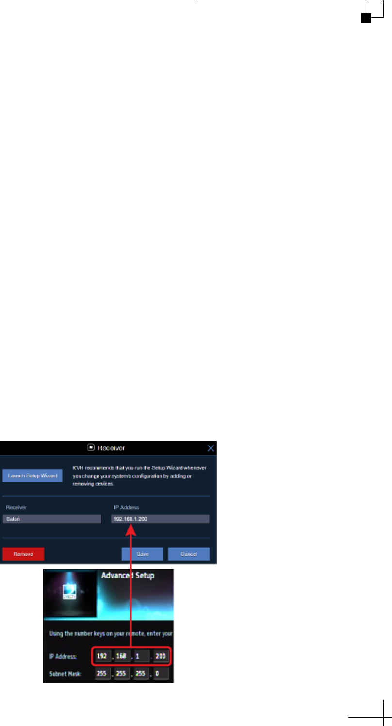
3. Assign a unique static IP address to the new receiver. See
“Configuring DIRECTV Receivers for Automatic Switching”
on page 38 for details.
4. Add the new receiver to the Autoswitch page of the web
interface. Enter the receiver’s static IP address and assign it a
friendly name (e.g., “Salon”).
NOTE: If the TV-Hub is unable to communicate with the receiver, try
resetting the receiver (press its red reset button or unplug it, wait 15 seconds,
then plug it back in and turn it on).
Figure 7-5 Adding a DIRECTV Receiver to the Autoswitch Page

TracVision TV5 User’s Guide
74
Switching Satellites
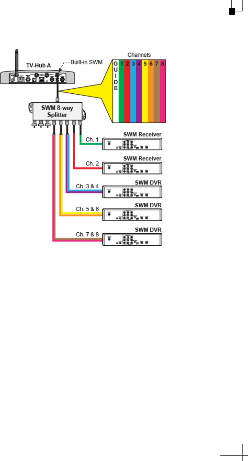
Understanding DIRECTV SWM Technology
The TV-Hub has a built-in DIRECTV single-wire multiswitch (SWM),
allowing you to connect multiple SWM-compatible receivers via a
single coax cable. At startup, the SWM allocates one of 13 channels
(TV-Hub A+) or eight channels (TV-Hub A) to each tuner it detects on
the cable. Each SWM receiver consumes one channel since it has a
single tuner. Each DVR consumes two channels, since it offers the
ability to record on one tuner while watching another.
Figure 7-6 DIRECTV SWM Technology (TV-Hub A+)
TracVision TV5 User’s Guide
75
Switching Satellites
Figure 7-7 DIRECTV SWM Technology (TV-Hub A)
TracVision TV5 User’s Guide
76
Switching Satellites
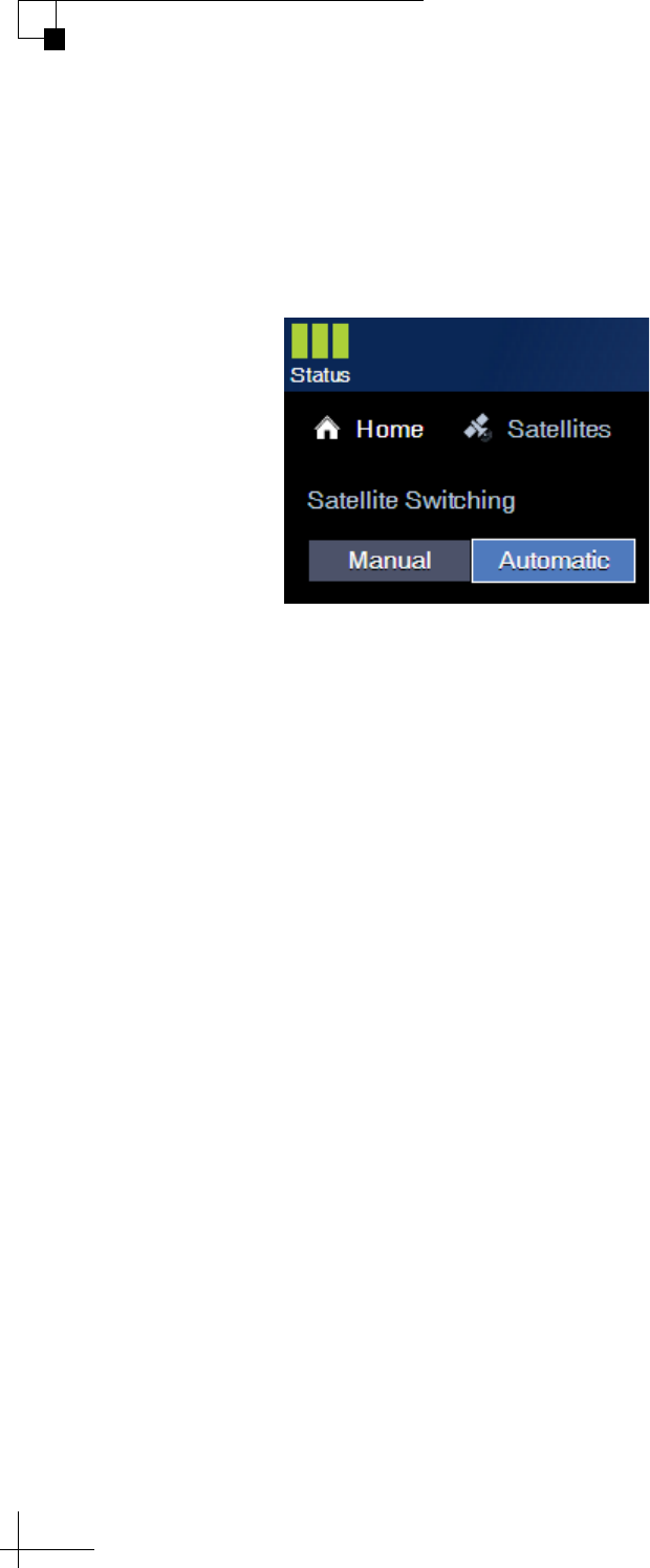
Selecting Automatic Switching Mode
To select automatic switching, simply select the Automatic satellite
switching mode at the Home page of the web interface.
Figure 7-8 Automatic Satellite Switching on Home Page
TracVision TV5 User’s Guide
77
Switching Satellites
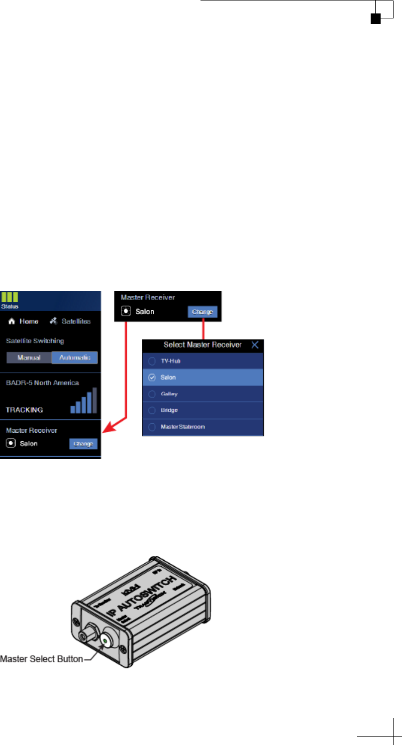
Selecting the Master Receiver
The master receiver controls satellite selection. The TracVision antenna
will switch between satellites automatically as you change channels
using the master receiver’s remote control. All other receivers will
only be able to select channels that are carried by the currently selected
satellite.
NOTE: The system must first be set to Automatic satellite switching mode
before you can select a master receiver. See “Selecting Automatic Switching
Mode” on page 76.
To make a different receiver the master, simply select it on the Home
page of the web interface.
Figure 7-9 Master Receiver Selection
As an alternative, if the receiver is connected to an IP AutoSwitch, you
can press the Master Select button on the IP AutoSwitch to make its
associated receiver the master.
Figure 7-10 IP AutoSwitch Master Select Button
TracVision TV5 User’s Guide
78
Switching Satellites
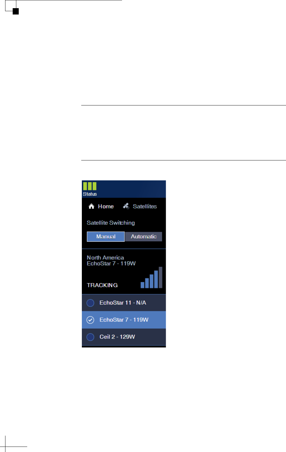
Manual Satellite Switching
Even if your system is set up for automatic satellite switching, you
always have the option to manually switch satellites at the Home page
of the web interface. Simply select the Manual satellite switching mode
then select the desired satellite from the displayed list of installed
satellites.
Figure 7-11 Manual Satellite Selection on Home Page
Important!
When you select Manual switching mode, the system no longer
responds to receiver satellite change commands. To restore automatic
switching, you need to select the Automatic satellite switching mode
at the Home page.
TracVision TV5 User’s Guide
79
Switching Satellites
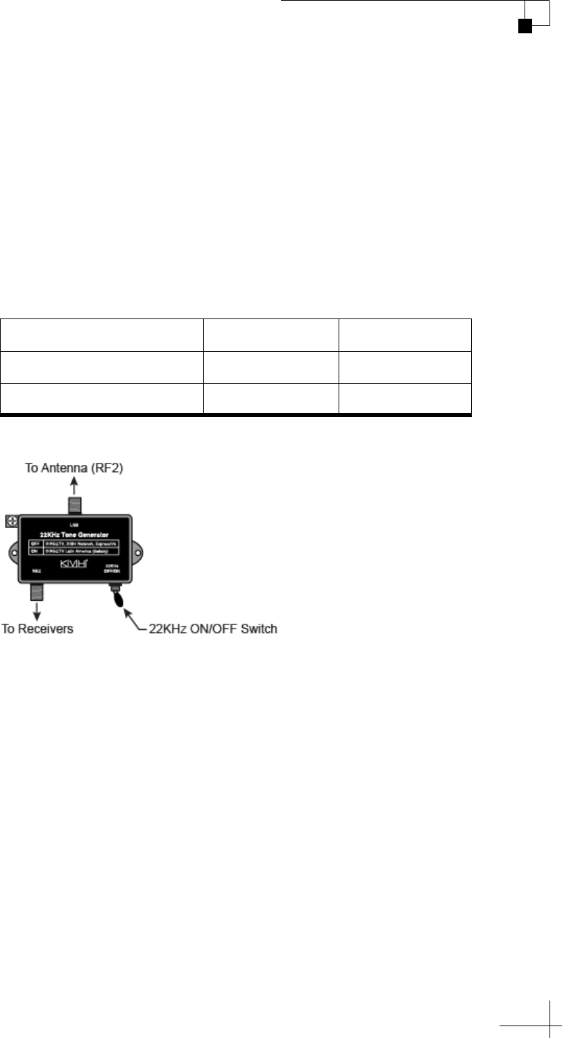
Tri-Americas Satellite Switching
If your antenna is equipped with a Tri-Americas LNB, you don’t need
to swap the LNB inside the antenna when you switch between
DIRECTV U.S. and DIRECTV Latin America services. The LNB can
receive satellite signals from either service.
However, when you switch between a DIRECTV U.S. satellite (101W
or 119W) and the DIRECTV Latin America satellite (95W), you need to
set the switch on the 22KHz tone generator to the correct position for
the selected service (refer to the Installation Guide for wiring details):
Figure 7-12 22KHz Tone Generator
Automatic switching is possible between the 101W and 119W
satellites, as explained in “Automatic Satellite Switching for
DIRECTV” on page 69. To switch between a DIRECTV U.S. satellite
and a DIRECTV Latin America satellite, you need to manually switch
using the web interface (see “Manual Satellite Switching” on page 78).
Service Satellite 22KHz Switch
DIRECTV U.S. 101W or 119W OFF
DIRECTV Latin America 95W ON

TracVision TV5 User’s Guide
81
Troubleshooting
8. Troubleshooting
This section identifies some basic problems along with their possible
causes and solutions. It also explains what the status lights and error
messages indicate, how to view the system logs and information, and
how to get technical support.
Contents
Basic Checks ...................................................................................................83
Status Information on the Home Page.............................................................85
TV-Hub Status Indicators.................................................................................87
IP AutoSwitch Status Indicator ........................................................................90
Error Messages ...............................................................................................91
System Logs ....................................................................................................95
System Information .........................................................................................98
Technical Support..........................................................................................100

TracVision TV5 User’s Guide
83
Troubleshooting
Basic Checks
If you are experiencing a problem receiving satellite TV with your
TracVision system, first check the following:
Check the System Status Information
Check the status indicators in the upper-left corner of the Home page
of the web interface, or check the three lights on the front of the
TV-Hub itself. All three should be lit solid green. See “TV-Hub Status
Indicators” on page 87 for details. Also look for an error message on
the Home page (see “Error Messages” on page 91).
Check for Satellite Signal Blockage
If the antenna is continuously searching for the satellite, check the area
around the antenna for blockage. The antenna needs an unobstructed
view of the sky to receive satellite signals. See “Avoiding Blockage” on
page 12 for details. Excessive dirt on the antenna and severe weather
can also affect reception. If there is no blockage, you might be located
outside the coverage area of the selected satellite (see www.kvh.com/
footprint), or the satellite’s elevation might be outside the antenna’s
range (see “Satellite Elevation Limitations” on page 55).
NOTE: The Home page of the web interface indicates the direction in which
the antenna is pointing.
Make Sure Your Receivers Are Set Up Properly
Your satellite TV receivers might need to be configured for the desired
satellite(s) and/or operating mode. Refer to “Receiver Settings” on
page 35 for details.
Check Power and Cables
Make sure power is applied to all system components. Also make sure
all cables are connected tightly. Refer to the Installation Guide for
wiring details.
Make Sure the Software and Satellite Library Are Up-to-Date
To update the system to the latest software version, refer to “Updating
the Software” on page 106. To update the satellite library, refer to
“Updating the Satellite Library” on page 104.
Adjust the LNB Skew Angle (Linear Systems Only)
If your antenna is not equipped with automatic skew, you need to
manually set the antenna’s LNB to the correct skew angle for the
selected satellite and your current location. Refer to “Adjusting the
LNB Skew Angle (Linear Only)” on page 27 for details.

TracVision TV5 User’s Guide
85
Troubleshooting
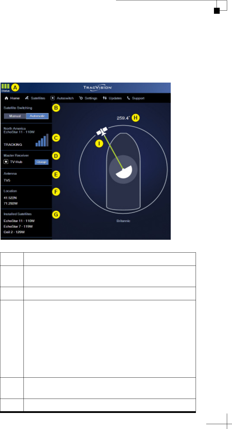
Status Information on the Home Page
The Home page of the web interface provides basic system status
information, as described below.
Figure 8-1 Home Page
Item Description
A Three status indicators match the physical status lights on
the TV-Hub (see “TV-Hub Status Indicators” on page 87)
B Current satellite switching mode: Automatic or Manual
C Currently selected satellite, satellite signal strength, and
general status of the antenna:
•Tracking
•Searching
• Cable Unwrap
• Initializing
• Boot
•Idle
•Error
D Currently selected master receiver (only shown in
Automatic satellite switching mode)
EAntenna model

TracVision TV5 User’s Guide
86
Troubleshooting
F Latitude/longitude of your current location, based on GPS
input or manual entry
G List of satellites currently installed in the antenna
H Your current true heading (requires NMEA input)
I Direction to the satellite, in relation to the bow of the
vessel; a green line between the antenna and the satellite
indicates the antenna is tracking the satellite
Item Description

TracVision TV5 User’s Guide
87
Troubleshooting
TV-Hub Status Indicators
Status lights on the Home page of the web interface and on the front of
the TV-Hub itself indicate the current status of the system and can
help you identify problems quickly.
Figure 8-2 TV-Hub Status Lights
During normal operation, all three lights should be lit green. The
following tables explain what the different light conditions indicate. If
an error condition exists, view the error message on the Home page of
the web interface (see “Error Messages” on page 91).
NOTE: During startup, each status light will illuminate orange for a few
seconds.
Important!
All three status lights will alternate orange whenever a software
update is in progress. Updates might take up to 40 minutes. Do not
turn off the system during this time.
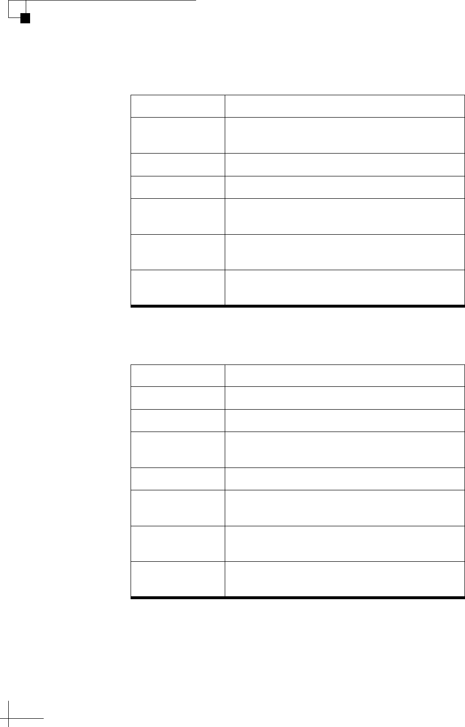
TracVision TV5 User’s Guide
88
Troubleshooting
TV-Hub Light
The table below explains what the TV-Hub light indicates.
Antenna Light
The table below explains what the Antenna light indicates.
State Description
Off TV-Hub is powered off, or there is no power
input
Green TV-Hub is operating normally
Green, Flashing TV-Hub is initializing
Orange, Flashing TV-Hub is operational, but a minor error exists
that you might be able to fix
Red TV-Hub is not operational; a major error exists –
contact KVH Technical Support
Red, Flashing TV-Hub is not operational; a major error exists
that you might be able to fix
State Description
Off No power input to the antenna
Green Antenna is tracking a satellite
Green, flashing Antenna is initializing or searching for a
satellite
Orange Antenna has been halted by a technician
Orange, flashing Antenna is operational, but a minor error exists
that you might be able to fix
Red Antenna is not operational; a major error exists
– contact KVH Technical Support
Red, Flashing Antenna is not operational; a major error exists
that you might be able to fix
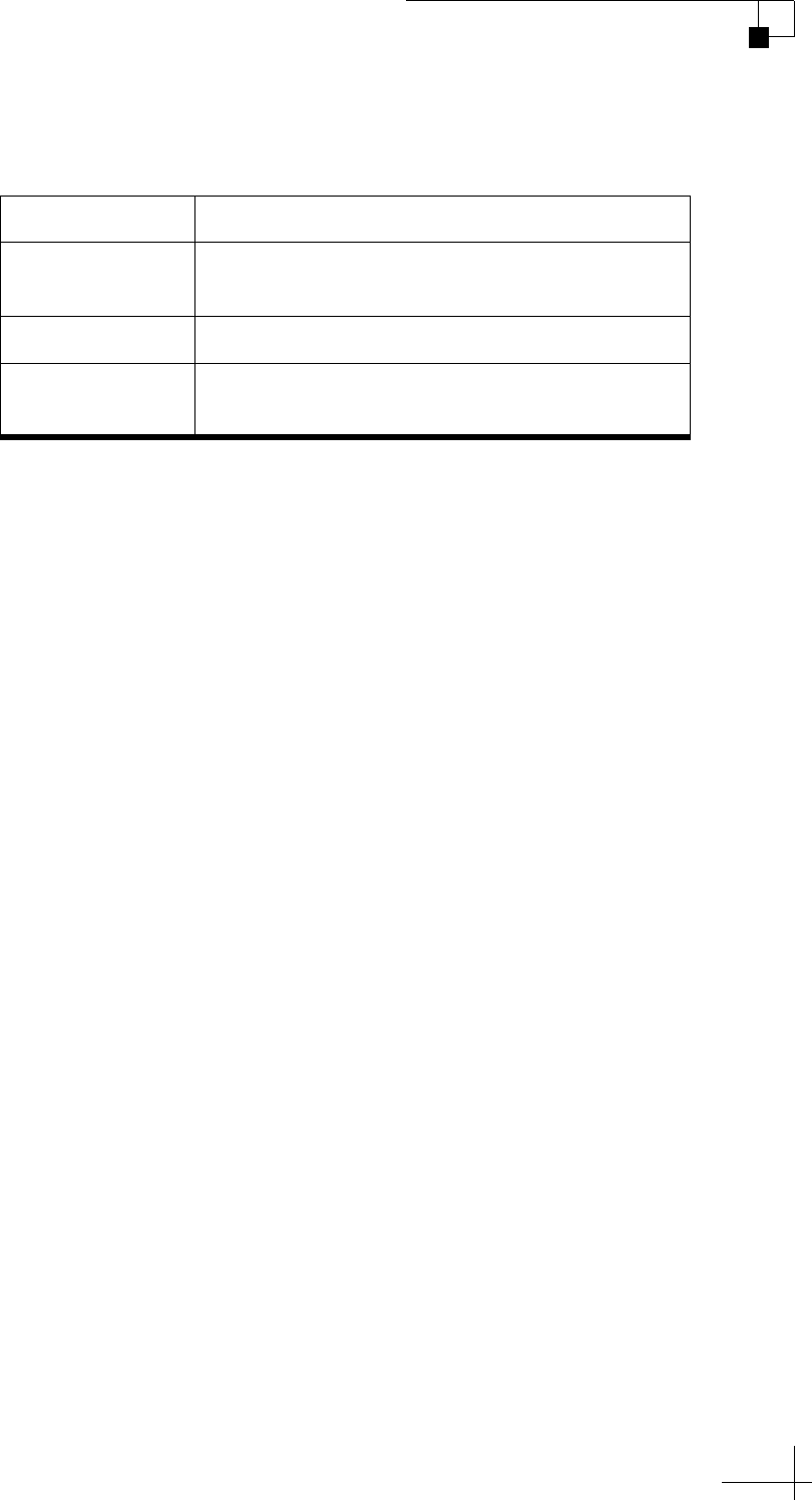
TracVision TV5 User’s Guide
89
Troubleshooting
Power Light
The table below explains what the Power light indicates.
State Description
Off TV-Hub is powered off, or there is no power
input
Green Good input power
Red, Flashing Input power is unacceptable; a major error
exists that you might be able to fix
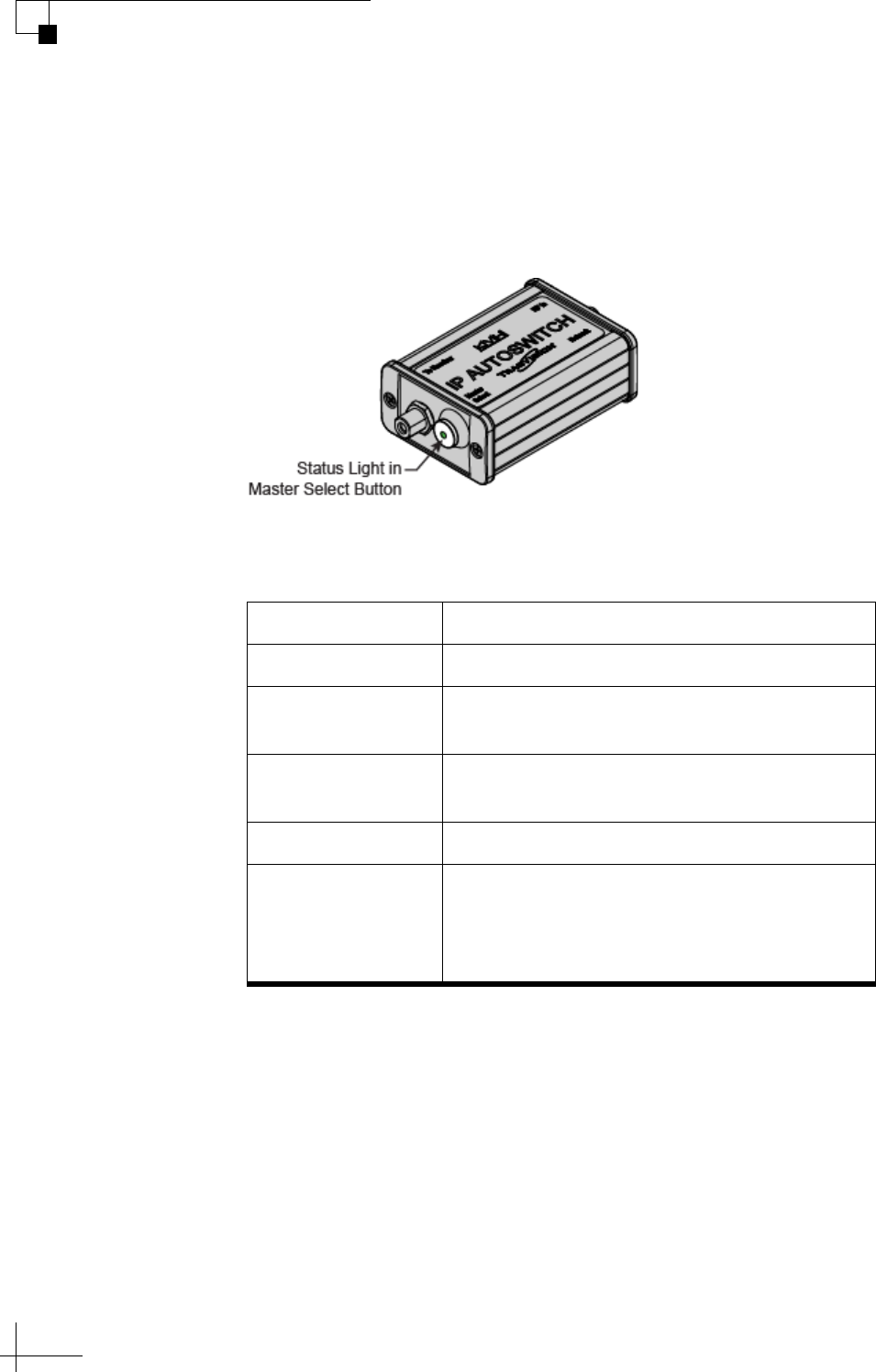
TracVision TV5 User’s Guide
90
Troubleshooting
IP AutoSwitch Status Indicator
A status light on the IP AutoSwitch indicates the current status of the
IP AutoSwitch.
Figure 8-3 IP AutoSwitch Status Light
The table below explains what the IP AutoSwitch status light
indicates.
State Description
Off No power input from the receiver
Green Registered with the TV-Hub and currently
selected as the master
Orange Registered with the TV-Hub but not currently
selected as the master
Orange, Flashing Initializing
Red Detected one of the following errors:
• Unable to communicate with the TV-Hub
• Network is not detected
• Unable to register with the TV-Hub
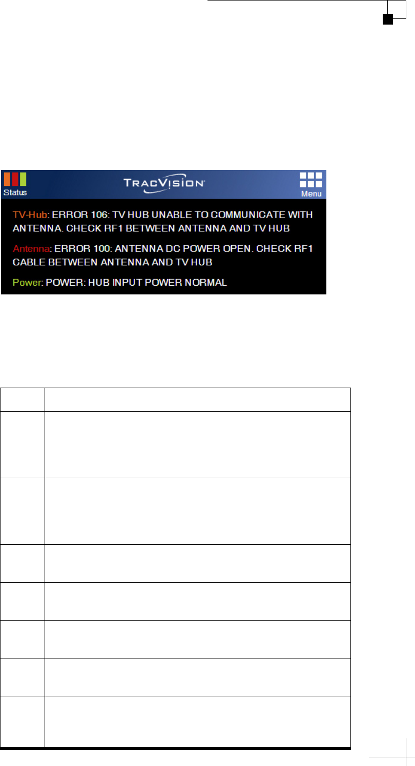
TracVision TV5 User’s Guide
91
Troubleshooting
Error Messages
If any of the Status indicators on the Home page of the web interface
are flashing orange, flashing red, or solid red, click on it to view the
error message.
Figure 8-4 Example of Error Messages under Status Indicators
The table below lists all of the possible error messages. Many of these
faults should only be repaired by a KVH-certified technician; contact
KVH Technical Support for assistance (see “Technical Support” on
page 100).
Error Description
100 There is an open circuit in the DC power wires running
between the antenna and the TV-Hub. The TV-Hub detects
no DC current feed to the antenna. Check the RF1 cable
between the antenna and the TV-Hub.
101 There is a short circuit in the DC power wires running
between the antenna and the TV-Hub. The TV-Hub detects
an overload condition. Check the RF1 cable between the
antenna and the TV-Hub.
102 The TV-Hub is not providing the proper DC voltage to the
antenna (should be 37.8-46.2 VDC). Contact KVH.
104 The software update file you selected is corrupt. Try a new
update file.
105 The TV-Hub is unable to read from or write to its
EEPROM. Contact KVH.
106 The TV-Hub has lost communications with the antenna.
Check the RF1 cable between the antenna and the TV-Hub.
107 The TV-Hub internal temperature exceeds acceptable
limits. If the problem persists, you might need to relocate
the unit to an area that provides better ventilation.

TracVision TV5 User’s Guide
92
Troubleshooting
108 An automated reboot of the TV-Hub is in process to
resolve low memory. No action is required.
109 The TV-Hub is running low on memory but it should be
able to recover without a reboot.
111 The TV-Hub is unable to initialize its built-in wireless
access point (WAP). Contact KVH.
119 The 24 VDC power to the internal SWM module is out of
range. DIRECTV outputs are disabled. Contact KVH.
124 The software update file you selected is not valid for your
antenna model. Try a new update file.
128 The software update failed. Retry updating the software. If
it fails again, check the RF1 cable between the antenna and
the TV-Hub.
129 One of the TV-Hub’s power supplies is out of range.
Contact KVH.
130 The TV-Hub DC input voltage is out of range (should be
10-30 VDC). Check the power source that is supplying DC
power to the TV-Hub.
131 The TV-Hub detects no DC current feed to the antenna,
following a period of normal operation. Check the RF1
cable between the antenna and the TV-Hub.
200 The antenna is not receiving adequate DC power from the
TV-Hub. Check the RF1 cable between the antenna and the
TV-Hub.
202 The antenna’s main board has lost communications with
the skew motor. Contact KVH.
203 The antenna’s main board has lost communications with
the azimuth and elevation motors. Contact KVH.
204 The antenna’s main board has lost RF communications.
Contact KVH.
205 The antenna’s azimuth motor has a power failure. Contact
KVH.
206 The antenna’s azimuth motor or limit switch failed.
Contact KVH.
Error Description

TracVision TV5 User’s Guide
93
Troubleshooting
207 The antenna’s elevation motor has a power failure.
Contact KVH.
208 The antenna’s elevation motor or limit switch failed.
Contact KVH.
217 The antenna’s skew motor has a power failure. Contact
KVH.
218 The antenna’s skew motor or limit switch failed. Contact
KVH.
221 The system is not receiving any data from the GPS.
Contact KVH.
222 The antenna’s internal temperature exceeds acceptable
limits. Turn off the system and allow it to cool.
223 The antenna’s main board has lost gyro calibration data. A
technician should calibrate the antenna’s gyros.
226 The antenna has lost RF communications. Contact KVH.
227 The antenna’s RF software might be corrupted. Contact
KVH.
228 The antenna has lost RF communications. Contact KVH.
229 The antenna’s RF software might be corrupted. Contact
KVH.
231 The antenna’s RF software might be corrupted. Contact
KVH.
232 The antenna’s RF software might be corrupted. Contact
KVH.
241 The antenna’s main board detects a power failure. Contact
KVH.
265 The GPS is unable to acquire a fix. Check for blockage or
RF interference around the antenna.
269 The main antenna processor detects that LNB voltage is
out of range. Contact KVH.
270 The azimuth or elevation gyro needs to be replaced.
Contact KVH.
272 The antenna’s main software does not match the antenna
type. Contact KVH.
Error Description
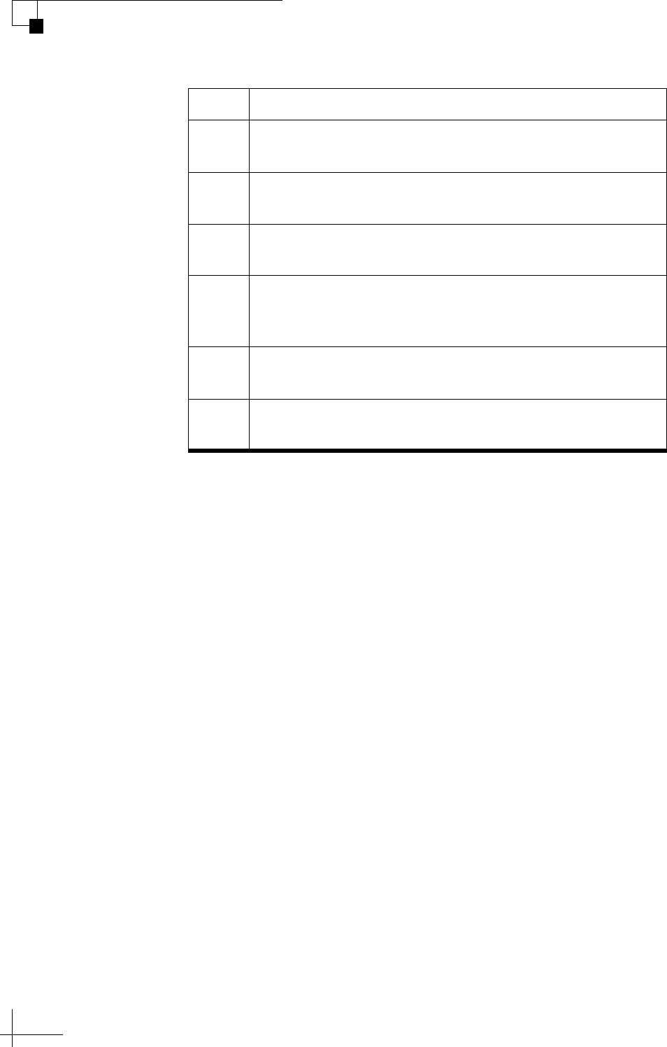
TracVision TV5 User’s Guide
94
Troubleshooting
273 The antenna’s motor software does not match the antenna
type. Contact KVH.
274 The antenna’s skew software does not match the antenna
type. Contact KVH.
275 The azimuth or elevation gyro needs to be replaced.
Contact KVH.
276 The antenna’s main board has lost accelerometer
calibration data. A technician should calibrate the
antenna’s accelerometer.
277 The search for a satellite has timed out. Restart the antenna
(see “Restarting the System” on page 109).
278 The antenna software update failed. Retry updating the
software. If it fails again, contact KVH.
Error Description


TracVision TV5 User’s Guide
96
Troubleshooting
Operational Log
The Operational Log, when initiated, records all messages that the
antenna system generates within a period of several minutes. To start
a new log or view the current log, select Operational Log on the
Support page of the web interface. Then select the desired option:
• View Current Log: This option simply opens the current
Operational Log. You can save this log as a text file
(filename: IPACU.serial.log) and send it to a technician or
KVH Technical Support.
• Start New Log: This option deletes the current Operational
Log and begins recording a new one.
• Restart System & Start New Log: This option deletes the
current Operational Log, restarts the antenna, and begins
recording a new Operational Log. This log will include the
system’s startup messages, which include the results of
various self-test routines.
When you start a new log, the progress bar increments until the log file
reaches the maximum allowed file size (100 KB). This normally
captures about 20 minutes of data.
Figure 8-5 Operational Log Options
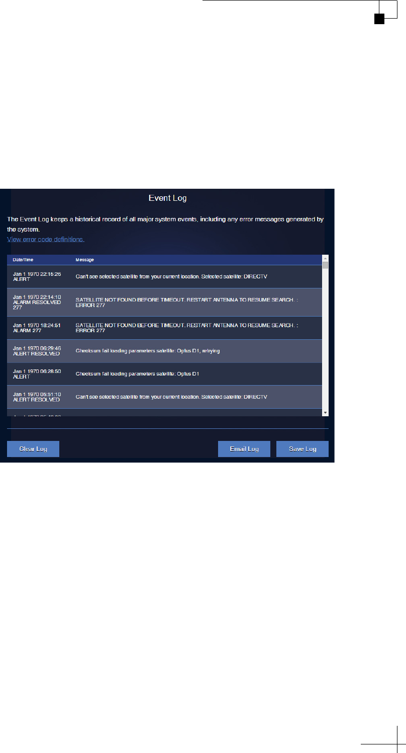
TracVision TV5 User’s Guide
97
Troubleshooting
Event Log
The Event Log keeps a historical record of all major system events,
including any error messages the antenna system generates. On the
Support page of the web interface, select Event Log. You can then save
the log file (filename: majorError.log) to your computer and e-mail it
to KVH Technical Support.
Figure 8-6 Event Log (Example)
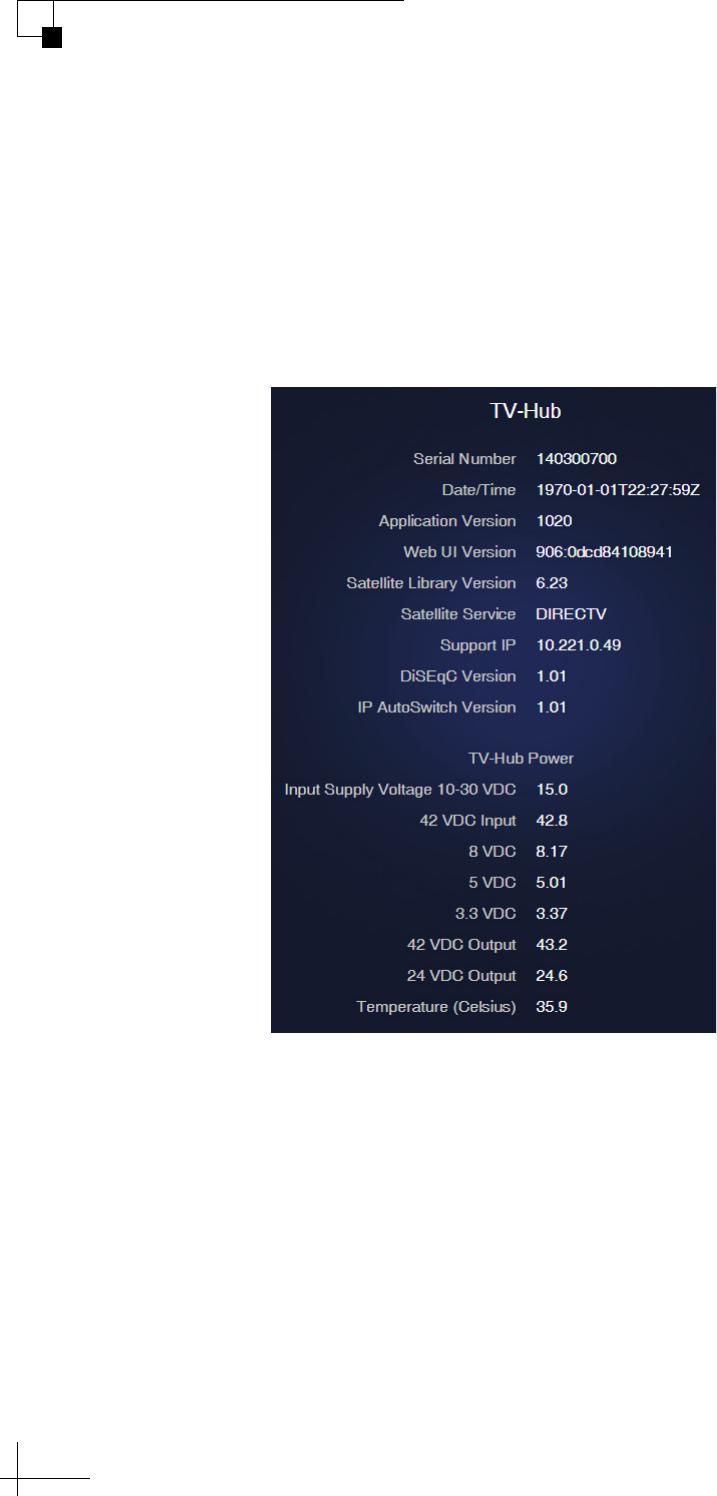
TracVision TV5 User’s Guide
98
Troubleshooting
System Information
You can find the serial numbers, software versions, voltages, and other
technical information for the TV-Hub and antenna on the Support
page of the web interface (go to Support > System Info). You will need
this information whenever you contact KVH Technical Support. It is
very useful for diagnostics.
Figure 8-7 System Info: TV-Hub (Example)
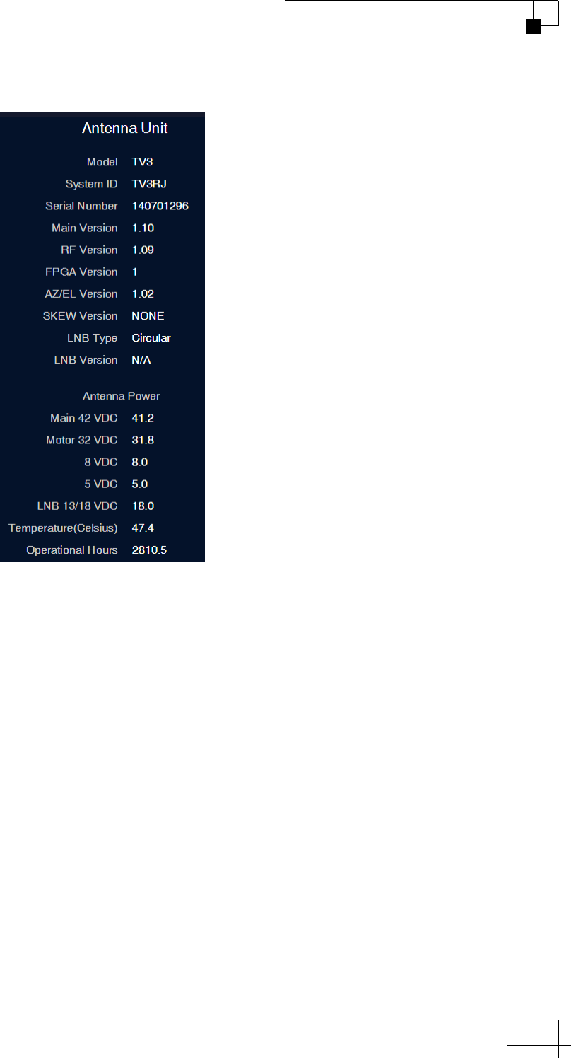
TracVision TV5 User’s Guide
99
Troubleshooting
Figure 8-8 System Info: Antenna Unit (Example)
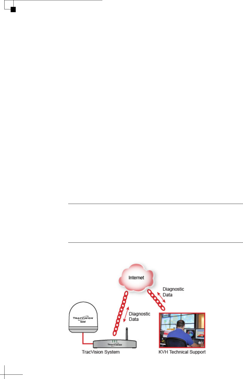
TracVision TV5 User’s Guide
100
Troubleshooting
Technical Support
The TracVision system is a sophisticated electronic device; only
specially trained KVH-certified technicians have the tools and
expertise necessary to diagnose and repair a system fault. Therefore, if
you experience an operating problem or require technical assistance,
please contact KVH Technical Support:
North/South America, Australasia:
Phone: +1 401 847-3327
E-mail: [email protected]
Europe, Middle East, Africa, Asia-Pacific:
Phone: +45 45 160 180
E-mail: [email protected]
Please have your system serial numbers and software versions handy
before you call (see “System Information” on page 98).
Remote Diagnostics
If your TV-Hub is connected to the Internet via an onboard network,
KVH Technical Support might be able to troubleshoot your system
remotely over the Internet.
Figure 8-9 Remote Access
Important!
KVH Technical Support will guide you through the process of
enabling remote diagnostics on the TV-Hub. Enable this connection
only when requested by KVH Technical Support.

TracVision TV5 User’s Guide
101
Maintenance
9. Maintenance
This section explains how to perform preventive maintenance to keep
the system in tip-top shape. It also explains how to update the software
and satellite library, and restart system components.
Contents
Preventive Maintenance ................................................................................103
Updating the Satellite Library........................................................................104
Updating the Software...................................................................................106
Corrective Maintenance.................................................................................108
Restarting the System ...................................................................................109
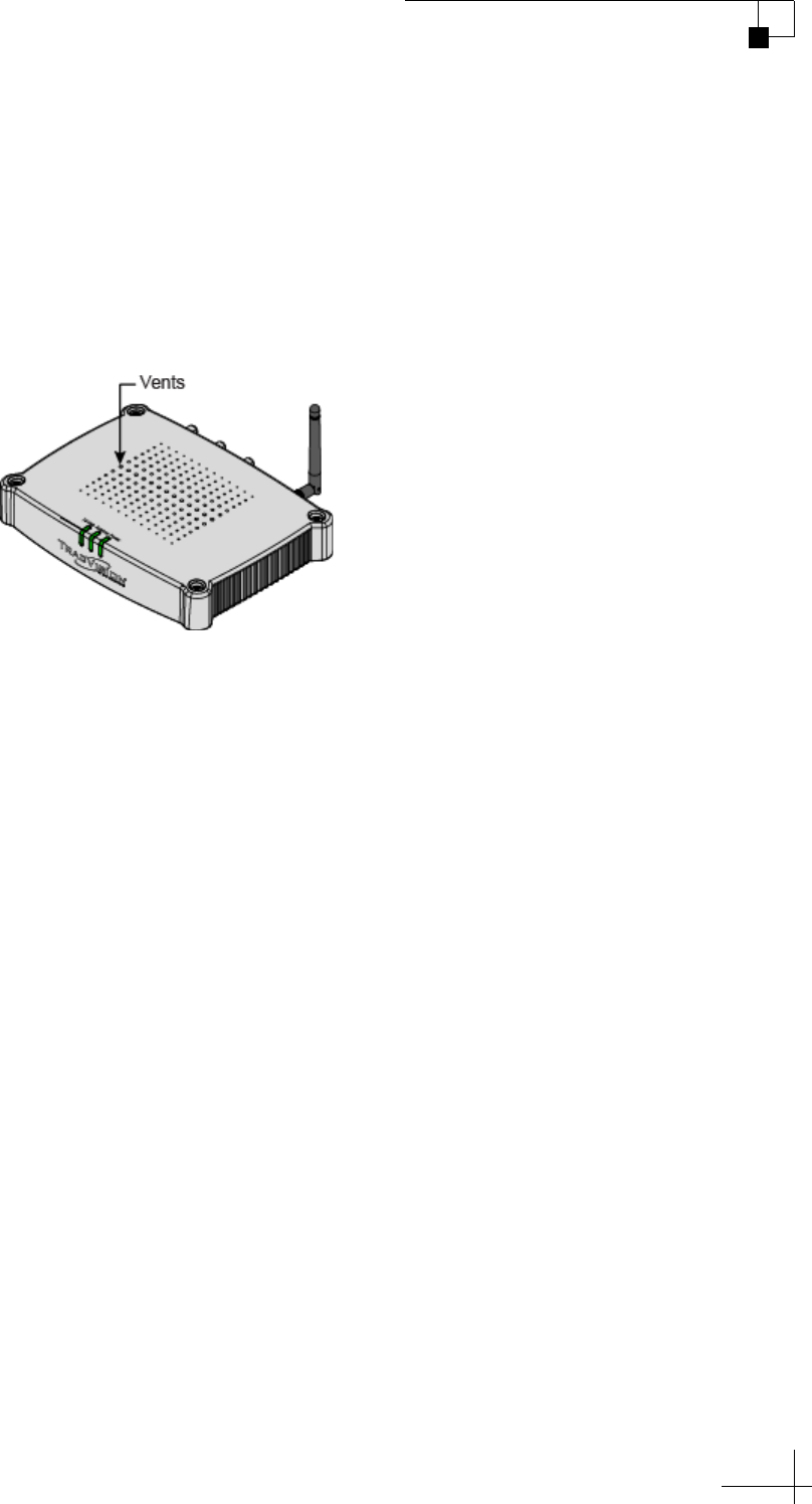
TracVision TV5 User’s Guide
103
Maintenance
Preventive Maintenance
The following tasks should be performed periodically to help maintain
peak performance:
•Vacuum the vents on the TV-Hub. Air needs to flow through these
vents to cool the electronic components and prevent overheating.
Figure 9-1 Vents on TV-Hub
• Clean the outside of the antenna with fresh water to remove grime.
Dirt buildup can affect reception of satellite signals. You may use
mild detergent, but avoid abrasive cleansers and high-pressure
water.
• Inspect the cable connections at the TV-Hub for any wear and tear.
Repair any damaged cables.
• Ensure the system is running the latest software version. See
“Updating the Software” on page 106 for details. Also make sure
the TV-Hub’s satellite library is up to date. See “Updating the
Satellite Library” on page 104 for details.

TracVision TV5 User’s Guide
104
Maintenance
Updating the Satellite Library
Service providers occasionally change the tracking parameters of their
satellites, necessitating an update to the data in the TracVision satellite
library. You can update your system’s satellite library to the latest
version at any time by downloading the file from KVH’s Update
server and uploading it to the TV-Hub. When you update the library,
the new version simply overwrites the previously installed version.
Use one of the following methods to update the satellite library:
Using an Onboard Network with Internet Access
If the TV-Hub is connected to an onboard network that has an Internet
connection, you can use that connection to download the library file.
Follow these steps:
1. Connect your computer to the same network as the TV-Hub.
2. At the Updates page of the web interface, select the satellite
library. Then select Download Update. This will download the
latest version of the library file onto your computer.
3. Select Install Update. Then navigate to and select the library
file (it has a .xml extension) saved on your computer. It will
only take a few seconds for the update to complete.
Using a Smartphone or Tablet
If you have an Apple iOS or Google Android smartphone or tablet,
and your device has an Internet connection, you can use the
TracVision TV/RV App to download the latest library file and upload
it to the system. You can download the App for free from the Apple
iTunes App Store or Google Play Store.
Important!
With the exception of user-defined satellites, updating the satellite
library overwrites any changes you have made to the satellites’
tracking parameters. All parameters for preset satellites revert to their
factory default settings.
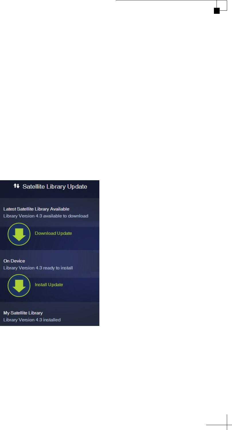
TracVision TV5 User’s Guide
105
Maintenance
Using a Computer with Internet Access
If your computer has an Internet connection, you can use that
connection to download the library file. Follow these steps:
1. Download the latest version of the library file onto your
computer from the KVH website (go to www.kvh.com/
Support/Product-Support-Library/Software-Updates).
2. Once you have downloaded the file onto your computer, use
the same computer to access the TV-Hub’s web interface (see
“Accessing the Web Interface” on page 14).
3. At the Updates page of the web interface, select the satellite
library then select Install Update. Navigate to and select the
library file (it has a .xml extension) saved on your computer. It
will only take a few seconds for the update to complete.
Figure 9-2 Satellite Library Update (Example)

TracVision TV5 User’s Guide
106
Maintenance
Updating the Software
KVH periodically releases new versions of software to enhance the
performance and capabilities of the system. You can update your
system to this latest software at any time by downloading the file from
KVH’s web server and uploading it to the system. When you update
the software, the new version simply overwrites the previously
installed version. A single software package includes updates to all
components in the antenna and TV-Hub.
Use one of the following methods to update the software:
Using an Onboard Network with Internet Access
If the TV-Hub is connected to an onboard network that has an Internet
connection, you can use that connection to download the software.
Follow these steps:
1. Connect your computer to the same network as the TV-Hub.
2. At the Updates page of the web interface, select the antenna.
Then select Download Update. This will download the latest
version of the software onto your computer via the onboard
network’s Internet connection.
3. Select Install Update. Then navigate to and select the update
file (it has a .kvh extension) saved on your computer.
4. Wait for the update to complete. It may take up to 45 minutes.
Using a Smartphone or Tablet
If you have an Apple iOS or Google Android smartphone or tablet,
and your device has an Internet connection, you can use the
TracVision TV/RV App to download the latest software and upload it
to the system. You can download the App for free from the Apple
iTunes App Store or Google Play Store.
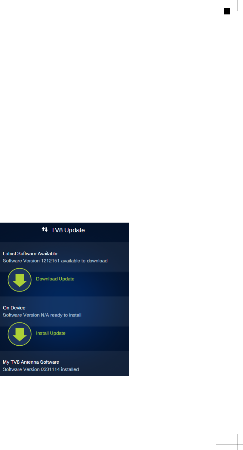
TracVision TV5 User’s Guide
107
Maintenance
Using a Computer with Internet Access
If your computer has an Internet connection, you can use that
connection to download the software. Follow these steps:
1. Download the latest version of software onto your computer
from the KVH website (go to www.kvh.com/Support/
Product-Support-Library/Software-Updates).
2. Once you have downloaded the file to your computer, use the
same computer to access the TV-Hub’s web interface (see
“Accessing the Web Interface” on page 14).
3. At the Updates page of the web interface, select the antenna
then select Install Update. Navigate to and select the update
file (it has a .kvh extension) saved on your computer.
4. Wait for the update to complete. It may take up to 45 minutes.
NOTE: The TV-Hub’s status lights will alternate orange while the update is
in progress.
Figure 9-3 Antenna Software Update (TV8 shown)

TracVision TV5 User’s Guide
108
Maintenance
Corrective Maintenance
If a system component fails, it will need to be replaced by a KVH-
certified technician. Instructions are provided with the replacement
part.
Important!
Field replaceable units should only be replaced by a trained, KVH-
certified technician. To find a technician near you, visit
www.kvh.com/wheretogetservice or contact KVH Technical Support
(see “Technical Support” on page 100).
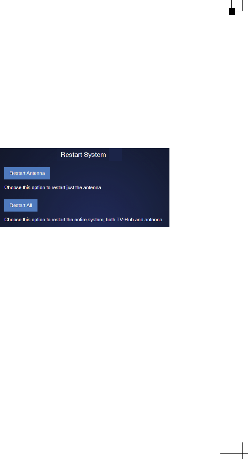
TracVision TV5 User’s Guide
109
Maintenance
Restarting the System
If you experience a problem with the system, you may need to restart
the hardware. You can restart the following system components at the
web interface (go to Support > Restart System).
• Restart Antenna: Restarts the TracVision antenna. Choose this
option whenever the antenna is unable to find the satellite.
• Restart All: Restarts both the TV-Hub and the antenna. Choose
this option if the problem cannot be isolated to the antenna.
Figure 9-4 Restart System Menu

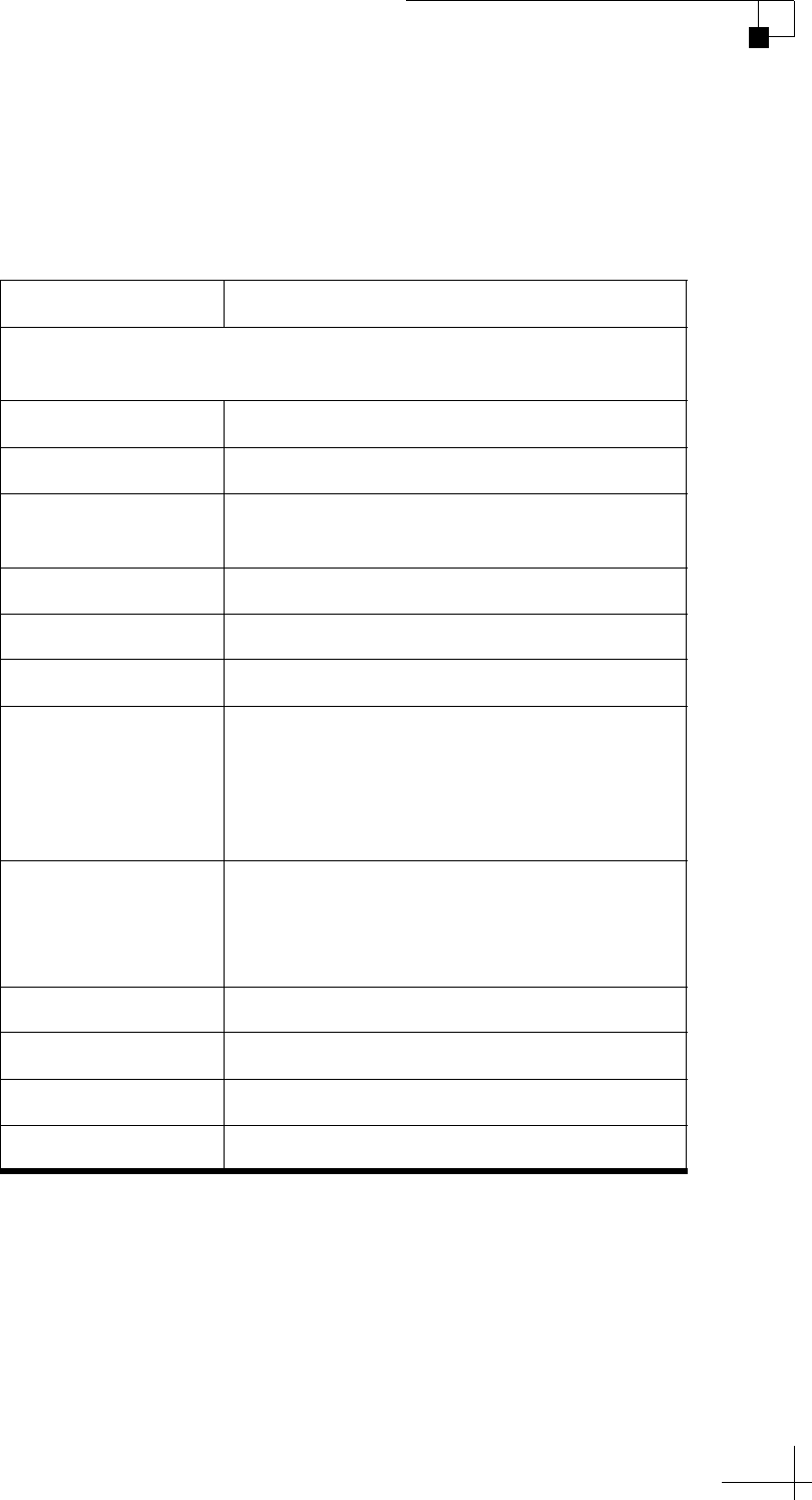
TracVision TV5 User’s Guide
113
Specifications
System Specifications
NOTE: All specifications are subject to change without notice.
TracVision TV5 Antenna Specifications
Attribute Rating
Meets Inmarsat BGAN operational, survival, vibration, and shock
specifications
Dimensions 19.2" (48.8 cm) OD x 20.9" (53.2 cm) H
Weight 25 lbs (11.3 kg)
Temperature Operating: -13°F to +131°F (-25°C to +55°C)
Survival: -13°F to +158°F (-25°C to +70°C)
Input power 42 VDC (from TV-Hub), 53 W nominal
Minimum EIRP 48 dBW (Ku-band)
Frequency range 10.7 to 12.75 GHz
Polarizations
• Vertical/horizontal polarity, high/low
band
• Simultaneous LHCP (left-hand circular
polarization) and RHCP (right-hand
circular polarization)
LNB options
• Linear Universal Quad
• DIRECTV L.A. Circular
•Circular
• Tri-Americas Circular
Elevation range 0° to 80°
Azimuth range 720°
Skew control Manual or Automatic
Cable connections 75-ohm type “F” connector
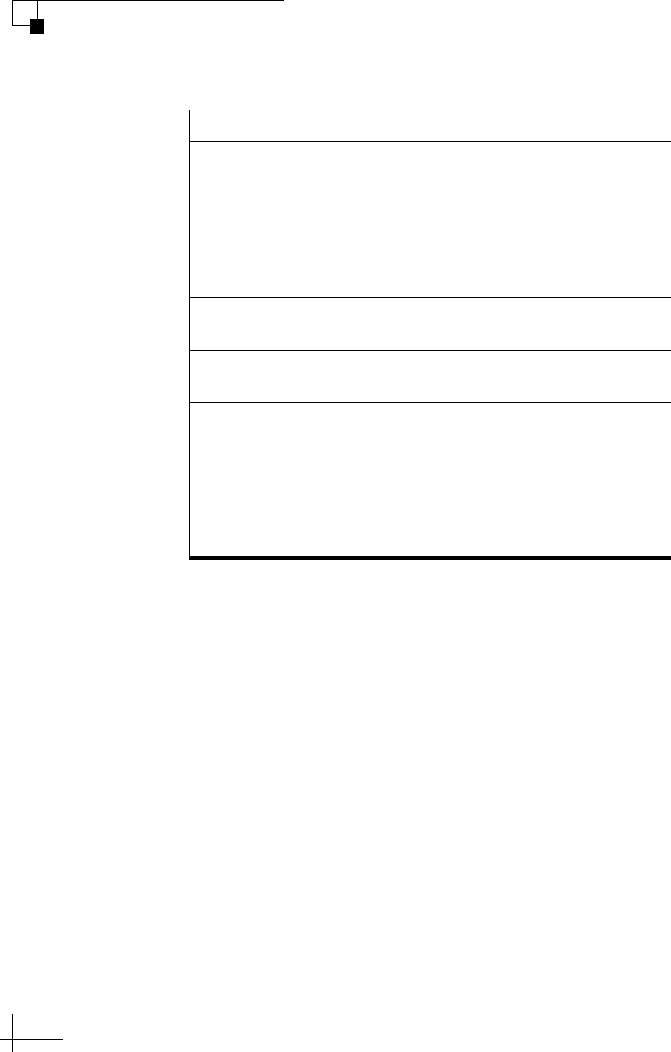
TracVision TV5 User’s Guide
114
Specifications
TV-Hub Specifications
Attribute Rating
Meets Inmarsat operational, survival, and shock specifications
Dimensions 9.3" (22.7 cm) W x 7.9" (20 cm) D x 1.7"
(4.4 cm) H
Weight TV-Hub A+: 2.8 lbs (1.3 kg)
TV-Hub A: 3.3 lbs (1.5 kg)
TV-Hub B: 2.1 lbs (1.0 kg)
Temperature Operating: 5°F to +131°F (-15°C to +55°C)
Survival: 5°F to +158°F (-15°C to +70°C)
Input voltage 12 VDC or 24 VDC (10-30 VDC required at
TV-Hub), 10 A max current
Output voltage 42 VDC
Supported RF1
cable to antenna
Up to 100 ft (30 m): RG-6
Up to 200 ft (60 m): RG-11
Supported NMEA
messages
NMEA 0183 (4800 baud): $--HDG, HDM,
HDT, OSD, THS, VHW, RMC
NMEA 2000: PGN 127250, PGN 129029

www.kvh.com
KVH Industries, Inc.
World Headquarters
Middletown, RI U.S.A.
Tel: +1 401 847 3327 Fax: +1 401 849 0045
Email: [email protected]
KVH Industries A/S
EMEA Headquarters
Kokkedal, Denmark
Tel: +45 45 160 180 Fax: +45 45 160 181
Email: [email protected]
KVH Industries Pte Ltd.
Asia-Pacific Headquarters
Singapore
Tel: +65 6513 0290 Fax: +65 6472 3469
Email: [email protected]
